Continue to Site

Welcome to EDAboard.com

Welcome to our site! EDAboard.com is an international Electronics Discussion Forum focused on EDA software, circuits, schematics, books, theory, papers, asic, pld, 8051, DSP, Network, RF, Analog Design, PCB, Service Manuals... and a whole lot more! To participate you need to register. Registration is free. Click here to register now.

Solar Lamp - help needed explaining circuit

Status
Not open for further replies.

Bluffer

Newbie level 6
Joined
Sep 24, 2012
Messages
12
Helped
0
Reputation
0
Reaction score
0
Trophy points
1,281
Location
England
Activity points
1,391
Hi,

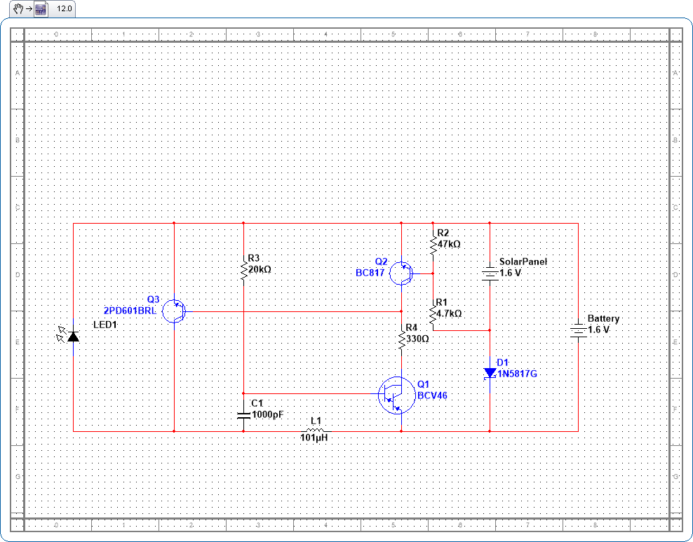
I've got a problem with my garden solar lamps so made a circuit diagram to help me understand what is going on before trying to repair it.

Having drawn the circuit I'm struggling to see how it works. My explanation below seems backwards ie the lights are on in the day and off at night. Can anyone help out and telll me what I'm doing wrong?

At night:

There is no voltage from the Solar Panel.
Q1 is on because there is never a voltage at its base. Q2 is off. This creates a voltage at the base of Q3 turning it on. As Q3 is on there is no voltage across the LEDs so they are off.

During daytime:

The Solar Panel supplies a voltage to the base of Q2 turning it on. As before Q1 is on but now there is no voltage at the base of Q3 so Q3 is off and a voltage across the LEDs turns them on.

Thanks for your time.


Hi,

Can't help you with your circuit.

Just a hint:
With scematics we usually draw that power (or data) travel from left to right,
and the most positive voltage is on top and negative on bottom of sheet.
This makes it easier to read.

Klaus
 

Just a hint:
With scematics we usually draw that power (or data) travel from left to right,
and the most positive voltage is on top and negative on bottom of sheet.
This makes it easier to read.

Yes.
The first thing I did was to make the upside-down schematic right side up then I rotated it so the battery and solar panel are on the left side and the LED is on the right side.
The second thing I did was to try to remove the annoying dots all over the schematic but I couldn't.

I think the schematic is drawn wrong because it will not oscillate to boost the voltage and its logic is backwards.
Many of my solar garden lights use this simple IC:
 

Attachments

  • pr4403.pdf
    198.8 KB · Views: 82

I think Q1 and Q3 form an oscillator, when Q2 in ON (output from solar cell) then it shorts out the base emitter junction of Q1 so stops the oscillations. Its a very crude circuit, the collector load for Q3 relying on the leakage resistance of Q2.
Do I get the cigar?
Frank
 

I haven't smoked a seegar for at least 30 years. In fact, I quit smoking a long time ago.

Two weeks ago I bought a package of 3 solar garden lights at low cost because they were in a Summer Clearance Sale.
One stopped working after only I week because its cheapo Chinese Ni-Cad battery rusted away. I used CLR on its holder contacts and replaced the battery with an American Ni-MH one that has a stainless and rustless case. These solar garden lights use the IC I linked.
The second light stopped after 10 days and I did the same repairs.
The third light still works in the evening but stops lighting during the night because its cheapo Chinese battery is crap with low capacity.
 

Status
Not open for further replies.

Similar threads

Part and Inventory Search

Welcome to EDABoard.com

Sponsor

Back
Top