Welcome to our site! EDAboard.com is an international Electronics Discussion Forum focused on EDA software, circuits, schematics, books, theory, papers, asic, pld, 8051, DSP, Network, RF, Analog Design, PCB, Service Manuals... and a whole lot more! To participate you need to register. Registration is free. Click here to register now.
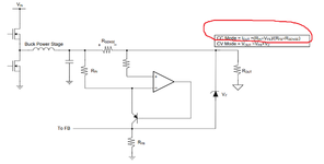
An example.
Let's say there is a voltage drop across the shunt of 0.1V
Then the Opamp regulates in a way that there is the same voktage drop (0.1V) across RIn.
This causes an emitter current of 0.1V/ Rin. Let's assume RIn to be 1k, then the emitter current is 0.1V/ 1k = 100 uA.
Let's assume the hFE of the bjt to be very high, then the collector current is the same as the emitter current = 100uA.
Since Vfb is considered constant, the RFb current is constant, too. Let's assume Vfb = 1.5V and Rfb = 2500.
Then I_Rfb = 600uA.
You have voltage regulation as long as there is current through the zener.
But zener current is 600uA - collector current. Now 600uA-100uA = 500uA.
If you increase the current: Vshunt becomes bigger, ... Icollector becomes bigger. Until collector current is 600uA..
Then you get into current limit mode.
Yes Klaus is correct....its the typical hi side current monitor.....
The way to look at it is..
In regulation, the + and - inputs of the opamp will be at the same voltage. (law of opamps with neg feedback, and since current into opamp input is zero)
...then V(Rsen) = V(RIN) (kirchoffs law, taking + and - to be at same potential)
...so I(RIN) = V(Rsen)/RIN (ohms law)
...also, I(RIN) = I(RFB) ('law' of NPNs when ON)
So then you can calculate VFB like that.
But to be honest, you do not show the error amplifier in the controller.......but presume reference on error amp = 2.5V....then it woudl act to regulate VFB to 2.5v......So there you have your starting point...from which you can back_calculate I(rsen)
This site uses cookies to help personalise content, tailor your experience and to keep you logged in if you register.
By continuing to use this site, you are consenting to our use of cookies.