syee10
Member level 3
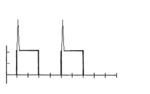
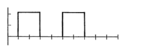
I have a square waveform as in the 1st figure which is not a smooth waveform. It has a high peak that i dun want in my real circuit. I want it to be a smooth square waveform as in the 2nd figure. So how am i going to convert the square wave with the peak to a smooth square waveform? Please assist me..