Vermes
Advanced Member level 4
It is a construction of sliding gate drive. The gate weighs approximately 500kg and it is 4,5m wide. The drive was home made. The base of construction was made of 4mm steel sheet, piece of steel tube and flat bar and few screws. After cutting to desired shape and welding, it should look like that:

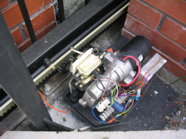
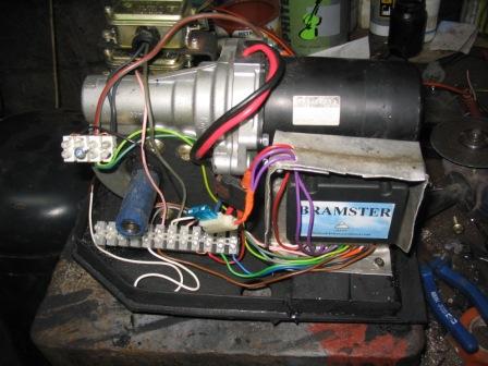
12V motor was removed from electronic steering assist system, but as well you can use a motor from wipers (the best 24V from a large car, such as a bus).

The gear wheel has to be lathed to the diameter of the motor output shaft. Tight fit of the elements was extra protected by a small weld (you can sand that if you have to remove the elements).
A driver with two remote controls was applied in this project. Aluminum plate acts as a kind of screen protecting against the influence of the motor on a radio receiver in the controller.
Limit switches behind the engine are commonly used with roller and lever.
12V supply, motor, driver, photocell and the warning light. Interesting element applied in this project is 12V 7Amh gel accumulator, which can be systematically charged by a power supply made of a 220/12V transformer with 15A rectifier bridge. The power supply is connected to the mains by a timer and charging the accumulator is periodically. The power supply is placed in the fence pole near the drive (in the electrical box) in order to eliminate interferences that may affect the sensitivity of the receiver.
Receiving antenna is a universal car antenna mounted on an auxiliary pole at a height of about 1m provides a range of about 20m.
The indication lamp – direction indicator, universal indicator to the moped/motorcycle.

Assembly:
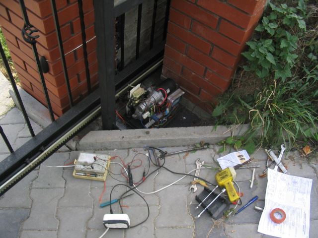
Base was attached using two hinges to the sheet mounted on the ground. The hinges were welded in one direction to allow for easy slipping the drive. Locking screw prevents from accidential slipping the drive. The hinges are welded in the rear part. In front, you can see a 12mm screw, which allows the adjustment, the gear – rack and, in the plan, it could leave the drive and release the gate in case of an accident.
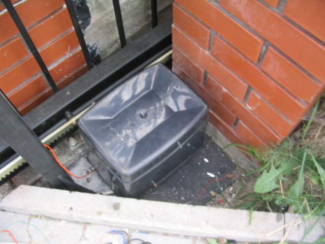
External housing – a trash can.
Time of gate opening/closing is 15s.
Link to original thread (useful attachment) – Napęd bramy przesuwnej