Continue to Site

Welcome to EDAboard.com

Welcome to our site! EDAboard.com is an international Electronics Discussion Forum focused on EDA software, circuits, schematics, books, theory, papers, asic, pld, 8051, DSP, Network, RF, Analog Design, PCB, Service Manuals... and a whole lot more! To participate you need to register. Registration is free. Click here to register now.

sine wave oscillator

Status
Not open for further replies.

soos2014

Newbie level 4
Newbie level 4
Joined
Jun 23, 2014
Messages
7
Helped
0
Reputation
0
Reaction score
0
Trophy points
1
Visit site
Activity points
53
I need help in designing a sine wave oscillator for frequencies 30-100 khz i tried lots of circuits but got distorted waveforms, amplitude variations and other non linearities with frequency variations. any suggestions?
 

Circuits with constant amplitude control have been previously suggested at edaboard. I'm sure you'll find some if you browse the respective threads.
 

I need help in designing a sine wave oscillator for frequencies 30-100 khz i tried lots of circuits but got distorted waveforms, amplitude variations and other non linearities with frequency variations. any suggestions?

You should specify your requirements because - as mentioned by FvM - there a many different oscillation circuits/principles.
For example:
* Frequency continuously tunable? Switchable? Single element control?
* Signal amplitude and quality (max. THD) ?
* Hardware: Operational amplifiers or transistors ?
* Supply voltage(s)?
 

How do you want to control the frequency between 30-100kHz?
Or is it to be a fixed frequency somewhere in that range?
 
Last edited:

Thanks for your reply. I need frequency to be variable in the range specified and this is my prime concern .The amplitude variations should not exceed 1/3 supply voltage over the whole frequency range.Supply voltages are no barrier but prefer +/-12V. Using a variable resistor preferably (single element control) and op amps are also preferred.
 

Question: You have specified the range 30-100 kHz. I suppose itis NOT 30 Hz but 30 kHz, correct?

I know only a few oscillator topologies having single-element tuning capabilities without disturbing the oscillation condition.
However, these circuits require two opamps. Is this a problem?
 
Last edited:

Correct! 30khz n not 30 hz. discrete components are no problem sir, but special ics may not be available to me. though i tried the 8038 and got distorted output too
 

Correct! 30khz n not 30 hz. discrete components are no problem sir, but special ics may not be available to me. though i tried the 8038 and got distorted output too

Since you have an 8038, then this is the simplist solution for you. For a better output shape, pay attention to the design notes & guidelines in the datasheets.

This claims distortion of down to 0.5% for sine wave with the various trimpots & resistor selections.

What levels of distortion are you hoping to achieve ?
 

I need help in designing a sine wave oscillator for frequencies 30-100 khz i tried lots of circuits but got distorted waveforms, amplitude variations and other non linearities with frequency variations. any suggestions?

Correct! 30khz n not 30 hz. discrete components are no problem sir, but special ics may not be available to me. though i tried the 8038 and got distorted output too

In your first post you mentioned that you want to DESIGN an oscillator - and in your last post you spoke about using an off-the-shelf integrated unit.
Moreover, my question was if you can afford to use TWO opamps. But be aware that for a maximum frequency of 100kHz the opamps used should be a gain-bandwidth product of some GHz.
 

Dear friend. I am working on the design of the oscillator using different oscillator types from colpitts, wien and the 8038. I use Multisims simulation program and then build the circuit.Multisims gives a satisfactory output but in practice rarley i had one. On the breadboard, I got a near sine wave with colpitts but for a limited range of nearly 20 khz +/- 5khz then signal gets attenuated and distorted in shape. Changing components values helped a little.
Op amps are no problem especially commonly used ones like 741, LM358 or LM324(preferred). Why should i need a high GBW if if my BW <100khz and most probably gain is unity or near so?

- - - Updated - - -

I prefer analog circuit rather than digital solution it is easier for me. i saw the article thx
 

Soos2014,
from your first post I have learned that you need an oscillator whichnis TUNABLE beween 30 kHz and 100 kHz.
Later you have mentioned that single-element control is needed.
Hence, for my opinion - the first step should be to choose a topology that allows single-element tuning.
This is not possible with WIEN type oscillators.
More than that, the mentined opamps (741, LM324, 358) cannot be used for oscillation fequencies up to 100kHz.
Furthermore, don´t overlook the slew rate capabilities of the selected opamps.
(I admit, that the requirement of some Ghz - as I have mentioned before - was by far too stringent. Perhaps 10 MHz are OK).
 
I remember seeing that the sine waveform from an old 8038 function generator IC had sharp triangle peaks. They caused the sinewave to look funny and make a low buzzing sound. But the distortion measured 0.5%. 0.001% distortion looks and sounds good.
 

A Wein-bridge type oscillator would give you the frequency range you want but you would need a dual-pot or dual-gang capacitor to tune the frequency.
 
A Wein-bridge type oscillator would give you the frequency range you want but you would need a dual-pot or dual-gang capacitor to tune the frequency.

Yes - in principle, I agree. (as I have mentioned above in post#12). However, within a smaller range (app. +- 10%), the amplitude-stabilized WIEN oscillator allows single-element tuning. However, in this case both resistors and capacitors must NOT be chosen equally. Then, the varaition of the oscillation condition is so small that it can be coverd by the amplitude stabilization.


FvM - your memory seems to be much better than mine.
Not so good as it seems. I remembered that there have been threads about single resistor tuned oscillators, but it took me several runs of the search tool to find (at least part of) it.
 

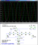
Below is my simulation of the GIC oscillator from one of FvM's references, which seems to do what the you want, using only a single resistor to vary the frequency. The frequency went from 28kHz to 106kHz with R5 varying from 150Ω to 3kΩ. The amplitude is reasonably stable with frequency.

The diodes act as clamps to help stabilize the output voltage.

The .ic V(Out)=1 command is only for simulation purposes to kickstart the oscillator.

Note that the frequency response versus resistance is non-linear so you may want to use a log pot to make the adjustment more linear with rotation.

The op amp characteristics somewhat affect the oscillator operation so beware of that if you use a different op amp with significantly different frequency response characteristics from the LT1211 used in the sim.

GIC Osc.gif
 
Last edited:
Hi Crutschow - one question: Did you also try to place the anti-parallel diodes across R2 only?
According to my experience, this should work better to keep the amplitude constant.
 

Status
Not open for further replies.

Similar threads

Part and Inventory Search

Welcome to EDABoard.com

Sponsor

Back
Top