Continue to Site

Welcome to EDAboard.com

Welcome to our site! EDAboard.com is an international Electronics Discussion Forum focused on EDA software, circuits, schematics, books, theory, papers, asic, pld, 8051, DSP, Network, RF, Analog Design, PCB, Service Manuals... and a whole lot more! To participate you need to register. Registration is free. Click here to register now.

Sine wave inverter voltage clipping (transformer saturation?)

Status
Not open for further replies.
Thanks for sharing! So do you think that the output capacitor resonated along with the secondary inductance? It has nothing to do with that silicon steel choke?

Could you give me more details about that choke inductor (size, wire, turns)? It has the same core used for regular laminated LF transformers?

I have some spare 1-1.5 kVA laminated core transformers and I wander if I could use their E+I cores to build such a choke inductor.

I also have some big iron powdered toroids (sendust blue cores). Aren't these more suitable for high frequency filtering?
 

Could you give me more details about that choke inductor (size, wire, turns)? It has the same core used for regular laminated LF transformers?
Its getting rather late here now.
Tomorrow I will measure it all up and give you the details.
 

*** UPDATE ***

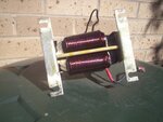
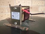
O/k here is a rather poor picture of the PWM choke, my cheap camera does not focus up close very well:

PWMCHOKE.JPG

PWMchoke2.JPG

It says 2.7mH on it, and I could not find any further details about it on the internet.
Testing here indicated it is closer to 3.75mH and it starts to curl up its toes towards saturation above around 28 amps.

It consists of two windings, each of two layers with a total turns count of 88 turns of 2.9mm OD copper wire. (22 turns per layer).

The core UU halves are tape wound grain oriented silicon steel. Tape width is 40mm, and the build 15mm. (core cross section 40 x 15mm).
It probably has an air gap, but the whole thing has been dipped in transformer varnish, so its impossible to take it apart to see, without destroying it.
 
Last edited:
Thank you very much for the photos and those comprehensive details. I have two 12/230 VAC transformers using a very similar core. What if I try to use them as is, only using their secondary (thick wires) windings?
 

If it was originally a transformer it will not have any air gap.
It may be possible to gap the core to enable it to work as a choke, but it will take some testing and experimentation.
 

I've just found a very interesting article written by Dave Wilson (Motorola, NXP/Freescale) about dead time distortion in full-bridge topology.

You may find the article on this www.mcjournal.com page or you can download an updated version from **broken link removed** website.

This is how a wave form "affected" by dead time distortion looks like:

dead time distortion.gif

and this is how my wave form looked like:

noload.jpg

I just can't wait to modify the MCU software to correct those PWM timmings. I'll keep you update with my results.
 

Status
Not open for further replies.

Similar threads

Part and Inventory Search

Welcome to EDABoard.com

Sponsor

Back
Top