Continue to Site

Welcome to EDAboard.com

Welcome to our site! EDAboard.com is an international Electronics Discussion Forum focused on EDA software, circuits, schematics, books, theory, papers, asic, pld, 8051, DSP, Network, RF, Analog Design, PCB, Service Manuals... and a whole lot more! To participate you need to register. Registration is free. Click here to register now.

Sine Wave Generation with SPI and TIM interrupt in STM32

Status
Not open for further replies.

uranyumx

Full Member level 1
Joined
Mar 5, 2011
Messages
96
Helped
1
Reputation
2
Reaction score
0
Trophy points
1,286
Activity points
2,053
Hello,

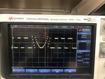
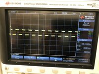
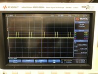
I want to generate a sine wave with a timer interrupt control. But I couldn't manage to get correct sine wave. I am using SMT32F767 as microcontroller and external DAC (DAC122S085CIMM/NOPB) . I am glad to hear your feedback about solution of the problem. I have also attached the screenshot of the oscilloscope when I probe at the DAC output.

Code:
uint8_t DAC_A_Write = 0x1; // DAC's A output is selected 0 0 0 1
uint8_t DAC_B_Write = 0x5; // DAC's B output is selected 0 1 0 1
uint16_t DACA_Buf; // Output A of the DAC is designated
uint16_t DACB_Buf; // Output B of the DAC is designated

uint32_t Wave_LUT[] = {
    2048, 2149, 2250, 2350, 2450, 2549, 2646, 2742, 2837, 2929, 3020, 3108, 3193, 3275, 3355,
    3431, 3504, 3574, 3639, 3701, 3759, 3812, 3861, 3906, 3946, 3982, 4013, 4039, 4060, 4076,
    4087, 4094, 4095, 4091, 4082, 4069, 4050, 4026, 3998, 3965, 3927, 3884, 3837, 3786, 3730,
    3671, 3607, 3539, 3468, 3394, 3316, 3235, 3151, 3064, 2975, 2883, 2790, 2695, 2598, 2500,
    2400, 2300, 2199, 2098, 1997, 1896, 1795, 1695, 1595, 1497, 1400, 1305, 1212, 1120, 1031,
    944, 860, 779, 701, 627, 556, 488, 424, 365, 309, 258, 211, 168, 130, 97,
    69, 45, 26, 13, 4, 0, 1, 8, 19, 35, 56, 82, 113, 149, 189,
    234, 283, 336, 394, 456, 521, 591, 664, 740, 820, 902, 987, 1075, 1166, 1258,
    1353, 1449, 1546, 1645, 1745, 1845, 1946, 2047
};

uint32_t z;

HAL_TIM_Base_Start_IT(&htim6);

void HAL_TIM_PeriodElapsedCallback(TIM_HandleTypeDef *htim)
{
  // Check which version of the timer triggered this callback and toggle LED
  if (htim == &htim6 )
  {
        HAL_GPIO_WritePin(DAC_CS_GPIO_Port, DAC_CS_Pin, GPIO_PIN_RESET);
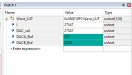
        DACA_Buf = DAC_A_Write<<12 | Wave_LUT[z]<<4;
        HAL_SPI_Transmit(&hspi2,(uint8_t*)&DACA_Buf,2,100);
        HAL_GPIO_WritePin(DAC_CS_GPIO_Port, DAC_CS_Pin, GPIO_PIN_SET);
        
        HAL_GPIO_WritePin(DAC_CS_GPIO_Port, DAC_CS_Pin, GPIO_PIN_RESET);
        DACB_Buf = DAC_B_Write<<12 | Wave_LUT[z]<<4;
        HAL_SPI_Transmit(&hspi2,(uint8_t*)&DACB_Buf,2,100);
        HAL_GPIO_WritePin(DAC_CS_GPIO_Port, DAC_CS_Pin, GPIO_PIN_SET);
        z++;
        if (z>=127)
        {
            z=0;
        }
    }
}
 

Attachments

  • IMG_8705.jpg
    IMG_8705.jpg
    1.9 MB · Views: 253

One consideration is other interrupt activity causing jitter in sinewave. Be sensitive to priority
assignment when you implement this.

Based on your waveform your indexing into your table incorrectly. Make sure your pointer to table
is sized and signed correctly. And that you are doing the round robin test correctly on end of table
handling.

Note there are ARM based processors out there with DMA and DAC that can do this all in background.
In fact do bursting sines with inter-burst controllable delay, and N cycle burst control. Just a thought.
All HW controlled once process is started/triggered.


Regards, Dana.
 
Last edited:

Hi,

The smaller problem: your table is not correct.
For 0 .. 127 it needs to be:
DAC_val = 2048 + rounded ( 2047 * sin( 360° * X / 128 )).
And the values may be stored in uint16_t.

The major problem is the wrong "shift 4 bits left".
(Your table values have LSB on the right, and so does the DAC expect it to be)
DACB_Buf = (uint16_t)DAC_B_Write<<12 | Wave_LUT[z]<<4;
Needs to be corrected to
DACB_Buf = (uint16_t)DAC_B_Write<<12 | Wave_LUT[z];
The same with channel A.

Z is globally declared. Not wrong.
The usual way is to declare it within the function using "static".

static uint16_t z;

Now it should work..
******
Although the STM32 has a barrel shifter inside....I'd rather:

uint16_t DAC_A_Write = 0x1000; ( or "uint16_t DAC_A_Write = 0x0000;" for synchronous DAC update)
uint16_t DAC_B_Write = 0x5000;

And then
DACA_Buf = DAC_A_Write | Wave_LUT[z];
DACB_Buf = DAC_B_Write | Wave_LUT[z];

Klaus

Added:
Next time give a link to the datasheet.
Best at the manufacturer's internet site. There is the latest version
And additional infirmations. Mind the additional documents.
 
Last edited:

Additionally any variable used inside main() also used in ISR declare as volatile.


Notice your DAC has issues on power up as well as FS glitch, considerations for you to address,
or ignore depending on how its used.

1618310411464.png


Regards, Dana.
 
Last edited:

Thank you @danadakk for the information!

Thank you @KlausST for your response about the code! Actually, should I create the sine wave with the lookup table or sine wave?

Attempt#1. Based on your suggestions on the sin function, I write a code,

uint16_t DACA_Buf; // Output A of the DAC is designated uint16_t DACB_Buf; // Output B of the DAC is designated uint16_t DAC_A_Write = 0x1000; uint16_t DAC_B_Write = 0x5000; uint16_t DAC_val; uint16_t I; void DAC_A_Conversion() { for (I = 0 ; I < 128 ; I++) { DAC_val = 2048 + round ( 2047 * sin( 360 * I / 128 )); HAL_GPIO_WritePin(DAC_CS_GPIO_Port, DAC_CS_Pin, GPIO_PIN_RESET); DACA_Buf = DAC_A_Write<<12 | DAC_val; HAL_SPI_Transmit(&hspi2,(uint8_t*)&DACA_Buf,2,100); HAL_GPIO_WritePin(DAC_CS_GPIO_Port, DAC_CS_Pin, GPIO_PIN_SET); } } void HAL_TIM_PeriodElapsedCallback(TIM_HandleTypeDef *htim) { // Check which version of the timer triggered this callback and toggle LED if (htim == &htim6 ) { HAL_GPIO_TogglePin(LED_GPIO_Port, LED_Pin); DAC_A_Conversion(); } }

Result. Then, I got a 30mV constant step function signal.

Attempt#2. After that, I tried to generate the sine wave with the lookup table.

#define NS 128 static uint16_t z; const uint16_t function[NS] = { 2048, 2145, 2242, 2339, 2435, 2530, 2624, 2717, 2808, 2897, 2984, 3069, 3151, 3230, 3307, 3381, 3451, 3518, 3581, 3640, 3696, 3748, 3795, 3838, 3877, 3911, 3941, 3966, 3986, 4002, 4013, 4019, 4020, 4016, 4008, 3995, 3977, 3954, 3926, 3894, 3858, 3817, 3772, 3722, 3669, 3611, 3550, 3485, 3416, 3344, 3269, 3191, 3110, 3027, 2941, 2853, 2763, 2671, 2578, 2483, 2387, 2291, 2194, 2096, 1999, 1901, 1804, 1708, 1612, 1517, 1424, 1332, 1242, 1154, 1068, 985, 904, 826, 751, 679, 610, 545, 484, 426, 373, 323, 278, 237, 201, 169, 141, 118, 100, 87, 79, 75, 76, 82, 93, 109, 129, 154, 184, 218, 257, 300, 347, 399, 455, 514, 577, 644, 714, 788, 865, 944, 1026, 1111, 1198, 1287, 1378, 1471, 1565, 1660, 1756, 1853, 1950, 2047 }; void DAC_A_Conversion() { for (z = 0 ; z < 128 ; z++) { HAL_GPIO_WritePin(DAC_CS_GPIO_Port, DAC_CS_Pin, GPIO_PIN_RESET); DACA_Buf = DAC_A_Write<<12 | Wave_LUT[z]; HAL_SPI_Transmit(&hspi2,(uint8_t*)&DACA_Buf,2,100); HAL_GPIO_WritePin(DAC_CS_GPIO_Port, DAC_CS_Pin, GPIO_PIN_SET); } } void HAL_TIM_PeriodElapsedCallback(TIM_HandleTypeDef *htim) { // Check which version of the timer triggered this callback and toggle LED if (htim == &htim6 ) { HAL_GPIO_TogglePin(LED_GPIO_Port, LED_Pin); DAC_A_Conversion(); } }

Result. Then, I got a 30mV constant step function signal too. In the watch window, the DACA_Buf value is updating.

So, did I miss something?
 

Hi,
should I create the sine wave with the lookup table or sine wave?
Lookup table. But I guess you calculate them using Excel or anything else. Thus I gave the formula.

For a first test I'd keep the timer interrupt callback function of post#1 .... with the little modifications.

*****
The waveform of post#1 can be explained:
For low values the sine values are shifted 4 times left ... equals in multiply by 16. Thus the huge steps.
But then the amplitude is too big and the upper 4 bits are used .... and the upper 4 bits get wrong values, not the command anymore.

Klaus
 

I use this sine wave generation code in Matlab. The source of the code is https://deepbluembedded.com/stm32-dac-sine-wave-generation-stm32-dac-dma-timer-example/ . So should I modify the sin function? So, how I can modify the sin function based on your suggestions? Actually, I modified and shared the code in post #5 so the only reason not getting correct sine wave output is related to the wrong lookup? By the way, I updated the lookup table in post 5 too. @KlausST

Code:
clear; clc;   % Clear The Previous Points
Ns     = 128; % Set The Number of Sample Points
RES    = 12;  % Set The DAC Resolution
OFFSET = 0;   % Set An Offset Value For The DAC Output
%------------[ Calculate The Sample Points ]-------------
T = 0:((2*pi/(Ns-1))):(2*pi);
Y = sin(T);
Y = Y + 1;   
Y = Y*((2^RES-1)-2*OFFSET)/(2+OFFSET);
Y = round(Y);                 
plot(T, Y);
grid
 

Generally speaking any transcendental function (the 'sin()' in your case) takes a lot of calculating. The MCU that you are using does which makes the calculations much (orders of magnitude) faster but it still means that it is calculating the same values over and over again.
A lookup table is a far better solution as no calculation is required as you are generating the output - you do all the calculating as you write the code and then only once.
You have 2Mbytes where you can store the LUT but if you feel you are running out of space, then you can halve or quarter the size of the LUT by using the various trig identities (e.g. sin(x) = -sin(x)) - read the table forward for the 1st quarter wave the read it backwards for the 2nd quarter wave; the 3rd quarter wave is read forward but you reverse the sign, and then read back with the sign reversal for the 4th quarter.
Also consider the actual number of steps you really need. This is something that only you can determine but don't get carried away with thinking that you need every degree or 3 - often the distortion you get from 5 degree steps is either negligible (for the application) or can be fixed with a LPF which you should have anyway (the DAC outputs a set of fixed 'steps' which generates a whole lot of high frequencies that you wont want).
Finally don't let the 12 bits of the DAC give you a false impression. If the DAC has an output of 0 to 5 volts (say), then each step in the DAC input value represents just over 1 mV - will your circuit really respond without noise to a step like that?
Susan
 

Hi,

Please use:
Code:
(wrong: T = 0:((2*pi/(Ns-1))):(2*pi);)
correct: T = 0:((2*pi/(Ns))):(2*pi);
edited: corrected formula
.. to calculate the table values
Added: The table values of post#5 make no sense at all. Neither in amplitude nor in timing.
Mind: if you have a table with 128 entries then:
Value(0) = value (64) = 2048 = zero cross.
Value(32) = 2048 + 2047 = 4095 = positive peak
Value(96) = 2048 - 2047 = 1 = negative peak
Value(127) = value(65) = negative half wave, value next to zero cross
Value(128) is not included in table at all. But if you imagine it's value then it needs to be the same as value(0)...for a non distorted continue of sinewave.
Use Excel to visualize your sine waveform.

And use the callback of post#1 (both your new "for" loops make no sense. Don't use a "for" loop)

Klaus
 
Last edited:

Added:
Rounding algorithm.
There are different rounding algorithms.
For lowest distortion sine you need to round exactly at 0.5 but symmetrically.

Means the rounded value of 0.5 should be 1
And the rounded value of (-0.5) should be (-1) ....to be symmetric.

Often rounding algorithms like int(value + 0.5) are used. This is not symmetric.
0.5 --> int(0.5 + 0.5) = int(1) = 1
But (-0.5) --> int(-0.5 + 0.5) = int(0) = 0 ..... not symmetric

Klaus
 

Table sample size performance -

1618498948270.png


64 samples

1618499619640.png


16 samples

1618500007998.png


No additional filtering done out of DAC other than imposed my limited Sle Rate of OpAmp and its GBW/

Regards, Dana.
 
Last edited:

Thank you @KlausST and @Aussie Susan!

Based on your formula, I got the same lookup table as in the post#1. So far, what I have

Code:
#define NS  128
const uint16_t Wave_LUT[NS] = { 2048, 2145, 2242, 2339, 2435, 2530, 2624, 2717, 2808, 2897,
                                      2984, 3069, 3151, 3230, 3307, 3381, 3451, 3518, 3581, 3640,
                                      3696, 3748, 3795, 3838, 3877, 3911, 3941, 3966, 3986, 4002,
                                      4013, 4019, 4020, 4016, 4008, 3995, 3977, 3954, 3926, 3894,
                                      3858, 3817, 3772, 3722, 3669, 3611, 3550, 3485, 3416, 3344,
                                      3269, 3191, 3110, 3027, 2941, 2853, 2763, 2671, 2578, 2483,
                                      2387, 2291, 2194, 2096, 1999, 1901, 1804, 1708, 1612, 1517,
                                      1424, 1332, 1242, 1154, 1068, 985, 904, 826, 751, 679,
                                      610, 545, 484, 426, 373, 323, 278, 237, 201, 169,
                                      141, 118, 100, 87, 79, 75, 76, 82, 93, 109,
                                      129, 154, 184, 218, 257, 300, 347, 399, 455, 514,
                                      577, 644, 714, 788, 865, 944, 1026, 1111, 1198, 1287,
                                      1378, 1471, 1565, 1660, 1756, 1853, 1950, 2047 };
static uint16_t z;

void HAL_TIM_PeriodElapsedCallback(TIM_HandleTypeDef *htim)
{
  // Check which version of the timer triggered this callback and toggle LED
  if (htim == &htim6 )
  {
    HAL_GPIO_TogglePin(LED_GPIO_Port, LED_Pin);
    HAL_GPIO_WritePin(DAC_CS_GPIO_Port, DAC_CS_Pin, GPIO_PIN_RESET);
        DACA_Buf = DAC_A_Write<<12 | Wave_LUT[z];
        HAL_SPI_Transmit(&hspi2,(uint8_t*)&DACA_Buf,2,100);
        HAL_GPIO_WritePin(DAC_CS_GPIO_Port, DAC_CS_Pin, GPIO_PIN_SET);
        
        HAL_GPIO_WritePin(DAC_CS_GPIO_Port, DAC_CS_Pin, GPIO_PIN_RESET);
        DACB_Buf = DAC_B_Write<<12 | Wave_LUT[z];
        HAL_SPI_Transmit(&hspi2,(uint8_t*)&DACB_Buf,2,100);
        HAL_GPIO_WritePin(DAC_CS_GPIO_Port, DAC_CS_Pin, GPIO_PIN_SET);
        z++;
        if (z>=127)z=0;
    }
}

I also initialized the timer. Then, I got 4.4V from DACA output and 0V from DACB output. In the watch window, the DACA_Buf and DACB_Buf are updating.
--- Updated ---

Thank you @danadakk for your report! How can I read your results? Can you explain them?
 

Attachments

  • Watch1.PNG
    Watch1.PNG
    9.1 KB · Views: 131

Hi,

Table still is wrong. But for tests it should be sufficient.

Show the complete code with the definition of all variables.

Please tell us:
* What´s the timing setup for the interrupt?
* What´s the SPI clock frequency?

Klaus
--- Updated ---

Hello,

I´m sorry I missed to correct the formula in post#9. Now done.

So again, please use:
Code:
 T = 0:((2*pi/(Ns))):(2*pi);

Klaus
 
Last edited:

(Timer clock frequency is 96.875 MHz) The timer settings of the interrupt is

Code:
static void MX_TIM6_Init(void)
{

  /* USER CODE BEGIN TIM6_Init 0 */

  /* USER CODE END TIM6_Init 0 */

  TIM_MasterConfigTypeDef sMasterConfig = {0};

  /* USER CODE BEGIN TIM6_Init 1 */

  /* USER CODE END TIM6_Init 1 */
  htim6.Instance = TIM6;
  htim6.Init.Prescaler = 96-1;
  htim6.Init.CounterMode = TIM_COUNTERMODE_UP;
  htim6.Init.Period = 100-1;
  htim6.Init.AutoReloadPreload = TIM_AUTORELOAD_PRELOAD_DISABLE;
  if (HAL_TIM_Base_Init(&htim6) != HAL_OK)
  {
    Error_Handler();
  }
  sMasterConfig.MasterOutputTrigger = TIM_TRGO_UPDATE;
  sMasterConfig.MasterSlaveMode = TIM_MASTERSLAVEMODE_DISABLE;
  if (HAL_TIMEx_MasterConfigSynchronization(&htim6, &sMasterConfig) != HAL_OK)
  {
    Error_Handler();
  }
  /* USER CODE BEGIN TIM6_Init 2 */

  /* USER CODE END TIM6_Init 2 */

}

I have attached the SPI settings. @KlausST
 

Attachments

  • spi settings.PNG
    spi settings.PNG
    22.2 KB · Views: 154

Hi,

What about the variables?

Is this correct?
* sck frequency about 24MHz?
* timer interrupt frequency 10kHz?

Klaus
 

Code:
uint16_t DAC_A_Write = 0x1000;
uint16_t DAC_B_Write = 0x5000;

uint16_t DACA_Buf; // Output A of the DAC is designated
uint16_t DACB_Buf; // Output B of the DAC is designated

static uint16_t z;

When I probe the DAC clock pin, I measure 10kHz clock frequency (IMG_8732). When I measure the toggling led frequency which is in the interrupt function, it is 5kHz (IMG_8733).
 

Attachments

  • IMG_8733.jpg
    IMG_8733.jpg
    1.9 MB · Views: 129
  • IMG_8732.jpg
    IMG_8732.jpg
    1.8 MB · Views: 161

Hi,

You can't initialize DAC_A_Write = 0x1000;
... and then shift it 12 bits left...

Please re read my posts above.

Klaus
 

It should be like this,

Code:
uint16_t DAC_A_Write = 0x0001;
uint16_t DAC_B_Write = 0x0101;
@KlausST

I am sorry I understand and fixed them. Now I get the sine wave. Its frequency is 80hZ. How is it related to the timer interrupt frequency?
 
Last edited:

Thank you @KlausST and @Aussie Susan!

Based on your formula, I got the same lookup table as in the post#1. So far, what I have

Code:
#define NS  128
const uint16_t Wave_LUT[NS] = { 2048, 2145, 2242, 2339, 2435, 2530, 2624, 2717, 2808, 2897,
                                      2984, 3069, 3151, 3230, 3307, 3381, 3451, 3518, 3581, 3640,
                                      3696, 3748, 3795, 3838, 3877, 3911, 3941, 3966, 3986, 4002,
                                      4013, 4019, 4020, 4016, 4008, 3995, 3977, 3954, 3926, 3894,
                                      3858, 3817, 3772, 3722, 3669, 3611, 3550, 3485, 3416, 3344,
                                      3269, 3191, 3110, 3027, 2941, 2853, 2763, 2671, 2578, 2483,
                                      2387, 2291, 2194, 2096, 1999, 1901, 1804, 1708, 1612, 1517,
                                      1424, 1332, 1242, 1154, 1068, 985, 904, 826, 751, 679,
                                      610, 545, 484, 426, 373, 323, 278, 237, 201, 169,
                                      141, 118, 100, 87, 79, 75, 76, 82, 93, 109,
                                      129, 154, 184, 218, 257, 300, 347, 399, 455, 514,
                                      577, 644, 714, 788, 865, 944, 1026, 1111, 1198, 1287,
                                      1378, 1471, 1565, 1660, 1756, 1853, 1950, 2047 };
static uint16_t z;

void HAL_TIM_PeriodElapsedCallback(TIM_HandleTypeDef *htim)
{
  // Check which version of the timer triggered this callback and toggle LED
  if (htim == &htim6 )
  {
    HAL_GPIO_TogglePin(LED_GPIO_Port, LED_Pin);
    HAL_GPIO_WritePin(DAC_CS_GPIO_Port, DAC_CS_Pin, GPIO_PIN_RESET);
        DACA_Buf = DAC_A_Write<<12 | Wave_LUT[z];
        HAL_SPI_Transmit(&hspi2,(uint8_t*)&DACA_Buf,2,100);
        HAL_GPIO_WritePin(DAC_CS_GPIO_Port, DAC_CS_Pin, GPIO_PIN_SET);
      
        HAL_GPIO_WritePin(DAC_CS_GPIO_Port, DAC_CS_Pin, GPIO_PIN_RESET);
        DACB_Buf = DAC_B_Write<<12 | Wave_LUT[z];
        HAL_SPI_Transmit(&hspi2,(uint8_t*)&DACB_Buf,2,100);
        HAL_GPIO_WritePin(DAC_CS_GPIO_Port, DAC_CS_Pin, GPIO_PIN_SET);
        z++;
        if (z>=127)z=0;
    }
}

I also initialized the timer. Then, I got 4.4V from DACA output and 0V from DACB output. In the watch window, the DACA_Buf and DACB_Buf are updating.
--- Updated ---

Thank you @danadakk for your report! How can I read your results? Can you explain them?

Basically the table shows you for small sized tables, down to just 16 values, you still get fairly
good harmonic distortion numbers.. The two spectrum plots show the difference between
64 sized table and 16 that distortion still < 5%, which depnedingh on what you are doing with
the sinewave can be pretty good. And you are using a 12 bit DAC, so your results for same sized
tables would be even better.

And a simple RC filter after DAC would get rid of even more harmonics.


Regards, Dana.
It should be like this,

Code:
uint16_t DAC_A_Write = 0x0001;
uint16_t DAC_B_Write = 0x0101;
@KlausST

I am sorry I understand and fixed them. Now I get the sine wave. Its frequency is 80hZ. How is it related to the timer interrupt frequency?


Your sine frequency = timer rate / table size

Regards, Dana.
 

Status
Not open for further replies.

Similar threads

Part and Inventory Search

Welcome to EDABoard.com

Sponsor

Back
Top