Paulpen
Newbie
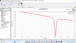
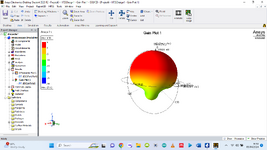
Please, I need some help to understand the result of my S11 result for the simulation of a second-order iteration Koch fractal antenna in HFSS. I have attached the S-parameter result and the 3D polar plot that shows the antenna gain. I am using a coaxial probe feed for the excitation
The confusing part is that I have a good gain (4.88db) but the s11 parameter is nothing like the ones I used to see which exceed the -10db point. Is something wrong with my scale or am I getting it wrong? Secondly, instead of seeing multiple resonant frequency responses, I am just seeing one, which is about 2.0xxx Ghz (not too far from the intended 1.8GHz).
Many other questions come to mind. For instance, given that the purpose of fractal antennas is to generate multiple resonant frequencies, is it possible that for certain frequencies, this will not happen, especially with higher-order iterations? I have varied the coaxial feed point position many times but the result does not change. On many occasions, it gets worse. This gain of 4.88db is kind of the best I have gotten so far. I have kind of given up on this second-order iteration and want to try the first-order iteration and compare the results.
Please, I need the help of the community to help me understand what is going on. I am not yet a pro in the antenna design space but I am ready to put in the work to understand the theory and how to build practical antennas. Thanks.