Continue to Site

Welcome to EDAboard.com

Welcome to our site! EDAboard.com is an international Electronics Discussion Forum focused on EDA software, circuits, schematics, books, theory, papers, asic, pld, 8051, DSP, Network, RF, Analog Design, PCB, Service Manuals... and a whole lot more! To participate you need to register. Registration is free. Click here to register now.

simulation loop antenna ads

Status
Not open for further replies.

Bou

Full Member level 3
Full Member level 3
Joined
Mar 6, 2013
Messages
159
Helped
0
Reputation
0
Reaction score
0
Trophy points
16
Visit site
Activity points
0
hello

I m looking for an example of simulation a loop antenna with ads momentum

help plz
 

No answers!!!!!!!!!
is that means it's not possible to simulate a pribted loop antenna with ads??!!!!!!!
 

Its not impossible to simulate an Planar loop structure in ADS..!! Do u have any references that u r following for ur design rules..?? Making a Printed loop in ADS is quite easy..!!
 

Its not impossible to simulate an Planar loop structure in ADS..!! Do u have any references that u r following for ur design rules..?? Making a Printed loop in ADS is quite easy..!!

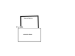
let's take fore example f=433 MHz and the design in the picture, my problem is to insert the "C tun ", I think is not possible because momentum gives only the pads!!
how can I simulate this antenna? loop.png
 

"C tun" must be a loading capacitor i believe ??

Generally If the design involves any lumped elements, u have to go for co simulation.. Works for designs like Wilkinson power divider were u design it in momentum and put ports at the points u want the lumped element to be placed..!! Create a component of design and use the component in schematic..!!

U can try doing it for this antenna design but i'M not sure if it will take for account while computing the radiation pattern..!!

10x for your answer,
can u send me an example of using a momentum design like a component in ads schematic?
 

Once u r finished with ur design in layout, Go to
momentum -> component -> create/ update, u can create a component by following these steps,

Once done, take a schematic window and go to library, U can find project option on left side, Find the name with which u save the file with ur component, Drag it and drop it to ur schematic..!! Use the ports that u have put in layout to connect ur capacitor or any other element and simulate..!!

Do comment on how the results are coming in terms of radiation pattern..!!

Hi
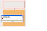
Ive tried to simulate this loop antenna but I always have an error " difference in the number of pins"
what kind of port we use for the definition of lumped component?
 

Its a regular port that u find in layout,.. when u place a port at a point and create a component, the component will have a pin at that point when imported to schematic..!!
 

Its a regular port that u find in layout,.. when u place a port at a point and create a component, the component will have a pin at that point when imported to schematic..!!

this is the error message
Sans titre.JPG
 

It's OK now I get the same result in S11 when I used Emmodel in the view of simulation,

what's the difference between the 3 views: layout, schematic and EMmodel?
 
Last edited:

  • Like
Reactions: Bou

    Bou

    Points: 2
    Helpful Answer Positive Rating

For ur case, i dont knw. In general we do it through post simulation in layout level..!! not sure if that option is available in schematic..!! Let me know if u find anything about it ..!!
 

OK

another question when we want to defin 2 pins that we want use for inserting a capacitor in the co simulation, that affects the momentum simulation!!! there is a way to desactivate them in the momentum simulation in aim to have just the pin place, do u see what I mean??
 

I didn't get u with the second part, When u do CO simulation, what you define in momentum or layout is simulated separately for its sparams and those results are used to complete the simulation with the component placed in schematic..!!
 

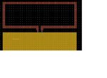
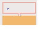
I don't know why I can't upload my project, Nevermind plz can u see those 2 pictures, in momentm I ve used 2 ports (P1-P2) and (P3-P4), but in reality I need only the first one; I used the second only in aim to insert a capacitor in the Co simulation, the presence of 2 ports modify my goal(simulation with 1 port and with 2 ports are not the same) ; for (P3 and P4) used for capacitor what type we must choose(I/O, I, Output)?im1.JPGim2.JPG
 

SpaceDust, I don't know if u see what I mean
 

Status
Not open for further replies.

Similar threads

Part and Inventory Search

Welcome to EDABoard.com

Sponsor

Back
Top