swolf
Newbie level 6
ota settling time
I have designed a Fully Differential Amplifier (FDA) with Switched Capacitance CMFB, which is used in pipelined ADC, but I wonder how to simulate the settling time of it. It is different from the OTA with continuous time CMFB because it's working in discrete time or just one half of the period.
I have read some materials and have already done some simulations about it, but I have still confused about it.
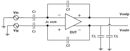
The figure attached below is from the paper "High speed, high gain OTA in a digital 90nm CMOS technology,NORCHIP,2005.pdf." It is used to test the settling time of the FDA. In the paper it said that "The closed loop testbench is straight forward except that an initial condition argument is used in the simulator to set the input common mode voltage."
The question is: Is it a good method to test the settling time?
If yes, then: 1, Should the initial condition file (.ic file in Spectre) contain the conditions of other nodes except the input pins?
2, How long should the period of the input square wave be (compared with the clock period of SC-CMFB)? Is it just a little longer than that of the clock period?
3, We just set the initial condition of the FDA, and it needs some time for the settling of the FDA since it uses SC-CMFB, so we have to monitor the settling time after that, then what's the condition of the input pins after some periods of the input square wave? is it still correct?
could anyone give me some hints? thanks in advance.
