Continue to Site

Welcome to EDAboard.com

Welcome to our site! EDAboard.com is an international Electronics Discussion Forum focused on EDA software, circuits, schematics, books, theory, papers, asic, pld, 8051, DSP, Network, RF, Analog Design, PCB, Service Manuals... and a whole lot more! To participate you need to register. Registration is free. Click here to register now.

Simulating Q of circular planar coil

Status
Not open for further replies.
I found that I needed an unusual high number of filaments

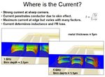
That was the effect that I see in Sonnet, too. Compared to the mesh that I use for RFIC inductors, this one needs more cells across the line width. When I think about this, the reason might be the ratio of skin depth (9µm @ 50MHz) and line width (6mm!). That ratio is less extreme in typical RFIC cases, which I usually analyze.


Anyway, I promised a new data point and here it is: with much finer meshing across the line, my Sonnet thick metal result seems to converge to Q ~380.

Best regards
Volker
 

@Volker: I completely agree about the extreme dimensions. Effectively, the wide track single turn coils have worse performance than a same are multi-turn design.

@Darkcrusher: I understood that the Q=350 number has been from a real measurement. How did you perform it? Are there possibly uncertainties, e.g. capacitor ESR involved?
 
@Volker: Q =380 is great news!!! Can you provide us more details about the simulation settings ?

Still 9% difference from reality.

Details measurement:
PCB loop was brought to resonance with fixed chip cap close to 50MHz
Measurement performed with inductive coupled loops, S21, VNA, -3dB bandwidth
Measurement has taken into account loading of the setup itself and Q of capacitor.
PCB loop was "hung" to avoid ennvironment effects

Possible uncertainties:
- Q variation of capacitor vs datasheet (software) value
- Solder joints
- Placement capacitor (eg inner vs outer diameter, current spreading vs edge port used in sim)
- etch angle

Still searching for CST, HFSS and ADS Momentum simulation results!
 
Last edited:

@Volker: Q =380 is great news!!! Can you provide us more details about the simulation settings ?

As discussed just above, the meshing is very critical here, because the current crowds on the extreme edges. You are looking at 0.01 Ohm effects and that correspond to 0.001 dB change in reflection. That is somewhat extreme and needs special settings.

Here are the Sonnet settings that I used: geometry sampling resolution (cell size) 0.1mm with thick metal model, conformal meshing, conformal subsection length = 1mm.
In the example above, I had used 0.5mm geometry sampling resolution, which is too coarse. That did not model the high edge current with enough detail, so that the effective conductor cross section and Q factor where over estimated. I can not go to much smaller subsections, because that will be slow. This is not an issue for normal RF circuits and it is not an issue for RFIC inductors.

We started the thread with your Axiem results, and why these are inconsistent. Let's come back to that:
From my first result above, where I analyzed in Sonnet with thin metal with 1 and 2 skin sheets and compared that to thick metal, you can see that thick metal is not much different from thin metal with 2 skin sheets. My interpretation of your difference between thin metal and thick metal in Axiem is that Axiem does thin metal with one skin sheet, which is reasonable for microstrip cases. The usual reason to use thick metal, the field difference between zero thickness and finite thickness, is not the issue it. It is just the number of skin sheets used to calculate the effective surface impedance of the thin sheet.

I think that your settings in Axiem should be: thick metal analysis, but to go to much finer mesh. Why don't you try that?


Still 9% difference from reality.

This statement does not make much sense, as long as we do not know the % error in your measurement.

If the purpose of this thread is to help you choosing the proper simulation settings for your simulator, I am happy to help. However, benchmarking EM solvers for accuracy needs an reference results that is exactly known, or where we know at least the error bars for the measured data.
 

Hi volker,

You are right about my % error statement, but I meant it 2 sided: either simulator and/or measurement error.

I will do my very best to provide % accuracy of the measurement, but it will be very hard due to some uncertainties.

I'll also try some different settings for AXIEM, but I thought my results converged.

I find it very interesting that it can be quite hard for this simple structure, to get a simulated Q wich is in agrrement with a measured one or vice versa.
 

I find it very interesting that it can be quite hard for this simple structure, to get a simulated Q wich is in agrrement with a measured one or vice versa.

For the simulator, your structure is not simple. With such a high Q factor, you look at very small losses, which correspond to 0.00x dB changes in the S-parameters. The metal trace is very wide compared to the skin depth, so that diskretizing into skin effect needs an extreme ratio between mesh size and total dimension. And finally, your inductor does not have a ground below, so that the thin metal defaults (microstrip case = one skin sheet only) do not apply.

For comparison: For RFIC inductors, where EM simulation is used a lot, the ratio of skin depth and conductor dimensions is much less extreme. I have attached a picture from one of my trainings on RFIC inductor analysis where you can see the high edge currents.
 

Attachments

  • where_current.JPG
    where_current.JPG
    69.7 KB · Views: 96

Thanks again Volker. I really appreciate your help.

I have 3 other coils for which I have measured Q. Maybe you can simulate these too ?

Dimensions are already given in this thread, but If you prefer I can just upload the .emp files...
 

Edge current 3D:

edge_current_3D.JPG

I got Q = 490 with AXIEM, which is a convergent result, but it is wrong since apparantly z-meshing is very minimal. Now I need to figure out how I can increase the meshing along the z-direction of the edge...
 

    V

    Points: 2
    Helpful Answer Positive Rating
Also important is etch angle:


I had 15% higher Q on 90 MHz for a slightly higher etch angle
 

Seems I cannot edit my start post.

Anyway:

Sonnet thick metal,fine mesh sim on 90 degree section: Q = 410 (update by support)
 

Seems this thread gets alot of attention.
I want to update the thread with the fact that my measured Q is slightly wrong since the Q of the used resonate capacitor has a huge uncertainty ( a factor 2 between software and measurement). The "measured" Q is lower than 350 and therefore there is larger percentage difference between simulated value

Can someone please simulate the Q with CST ?
 
Last edited:

I performed a Quickfield simulation of a trace with an edge shape according to the above cross-section and got Q values around 385.

In addition to the accuracy limits set by the meshing, I found out that there's also a numerical resolution problem when large parts of the conductor area don't carry considerable current density. The effect could be explained, if Quickfield is using 32-bit float for the simulation.
 

Attachments

  • coil_30_6_real1.pdf
    100.7 KB · Views: 87

Status
Not open for further replies.

Part and Inventory Search

Welcome to EDABoard.com

Sponsor

Back
Top