TimmyBB
Newbie level 1
Hello,
I am trying to do simulation of a single net in an lvds pair with CST design studio. The outputbuffer-ibis model used is the following: lvds25_ro_p0_v0 which can be found in the attached ibis model of the altera stratix IV device. (Stratix4.zip)
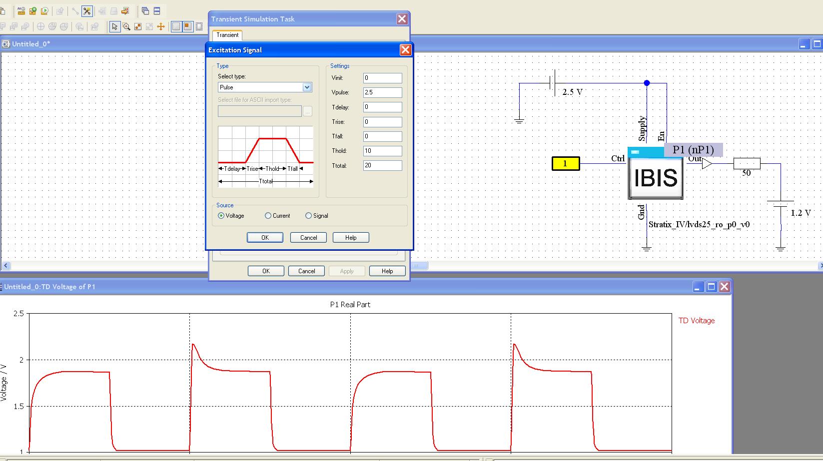
My setup in CST can be found in the attached LVDS.jpg
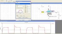
To simulate the single ended net in CST, I terminated the output with a 50Ohm resistor to Vfixture, which is 1.2V.
The excitation signal on the ctrl pin of the ibis block is defined as 50MHz with a voltage level of 2.5V. But I am not quite sure if this is correct... I would expect that the voltage levels, and rise/fall times would come out of the ibis outputbuffer block... I connected also the Supply and En pin of the IBIS block to 2.5V. I also don't know if this is correct.
Then at the bottom of the image, you can find the simulated waveform at the output... This is really not what I expected... I expected a voltage waveform of 50Mhz (this is correct) with Vol = 1V and Voh = 1.4V. And also the waveform is not uniform, I have an overshoot every other pulse.
Any suggestions?
Thx,
Tim
I am trying to do simulation of a single net in an lvds pair with CST design studio. The outputbuffer-ibis model used is the following: lvds25_ro_p0_v0 which can be found in the attached ibis model of the altera stratix IV device. (Stratix4.zip)
My setup in CST can be found in the attached LVDS.jpg
To simulate the single ended net in CST, I terminated the output with a 50Ohm resistor to Vfixture, which is 1.2V.
The excitation signal on the ctrl pin of the ibis block is defined as 50MHz with a voltage level of 2.5V. But I am not quite sure if this is correct... I would expect that the voltage levels, and rise/fall times would come out of the ibis outputbuffer block... I connected also the Supply and En pin of the IBIS block to 2.5V. I also don't know if this is correct.
Then at the bottom of the image, you can find the simulated waveform at the output... This is really not what I expected... I expected a voltage waveform of 50Mhz (this is correct) with Vol = 1V and Voh = 1.4V. And also the waveform is not uniform, I have an overshoot every other pulse.
Any suggestions?
Thx,
Tim