Continue to Site

Welcome to EDAboard.com

Welcome to our site! EDAboard.com is an international Electronics Discussion Forum focused on EDA software, circuits, schematics, books, theory, papers, asic, pld, 8051, DSP, Network, RF, Analog Design, PCB, Service Manuals... and a whole lot more! To participate you need to register. Registration is free. Click here to register now.

Simulated Antenna Efficiency

Status
Not open for further replies.

AndreyG

Full Member level 4
Joined
May 10, 2010
Messages
196
Helped
27
Reputation
54
Reaction score
27
Trophy points
1,308
Location
Vancouver, Canada
Activity points
2,946
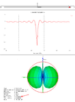
I modeled a structure in MWS - parallel plate transmission line shorted from both ends.
I contemplated using it as a radiator.
I can match such structure to 50 Ohm but model shows low Radiating Efficiency.
How can this be if I use Perfect Electrical Conductor in Free Space?

(I used to think that Radiating Efficiency less then 1 is result of energy loss due to finite conductivity of radiator and losses in dielectrics. My model have none. Where the energy goes?)
 
Last edited:

sounds interesting! A shorted transmission line cannot be matched to 50ohms very easily. I think you are right to look for a good efficiency since it seems to be matched. I would try the same thing with an open ended line to see what happens. Will you get the same result? One other possibility for losses is the substrate but it should be very low unless the frequency is very high or the substrate has a high loss tangent.

more details on your model and some numbers (s11 etc.) would help.
 

Basically I model a slot in conductive plane.
Slot can be interpreted as transmission line shorted from both ends.
When conductive plane is wide slot is efficient radiator.
When I make conductive plane narrow slot is still matched to 50 Ohm but Radiation efficiency drops dramatically.
In my model conductive plane is made from Perfect Electric Conductor.
No dielectrics, no substrates.
Where does the energy go?
 

Attachments

  • narrow slot result.PNG
    narrow slot result.PNG
    63.1 KB · Views: 64

What about the radiation boundary? do you need to define it in MWS. Because that could be the reason why it doesn't work when you make it smaller.

---------- Post added at 20:36 ---------- Previous post was at 20:30 ----------

One more idea: as far as I know, with slot antennas the metal around them needs to be infinite (in theory). When you make it small, the conductive parts stop acting like a ground as they are now the right size to be a dipole antenna.

So having a large metal area around your slot is good practice when you build slot antennas. however this may not be the cause for no radiation. it is more likely to be about how the software interprets the radiation boundary for your model. if it is too close to the antenna these errors should be expected.
 
Last edited:

For Boundaries I use Open/add space.
As you correctly assumed boundaries change with size of the modeled object.
I prevented the boundaries from decreasing by placing small blocks of vacuum half wavelength away from the object - in all directions. I got the same results

---------- Post added at 19:43 ---------- Previous post was at 19:37 ----------

>>One more idea: as far as I know, with slot antennas the metal around them needs to be infinite (in theory). When you make it small, the conductive parts stop acting like a ground as they are now the right size to be a dipole antenna.

>> So having a large metal area around your slot is good practice when you build slot antennas.

I am aware of this. And if you make slot in thin metal piece it is poor radiator.
I am trying to figure out why.
Where the energy goes?
 

If having larger boundaries didn't work, I am out of ideas for now. The only thing I could suggest would be to go back to using a larger conductor around your slot. This is common practice anyway.
 

Status
Not open for further replies.

Part and Inventory Search

Welcome to EDABoard.com

Sponsor

Back
Top