Continue to Site

Welcome to EDAboard.com

Welcome to our site! EDAboard.com is an international Electronics Discussion Forum focused on EDA software, circuits, schematics, books, theory, papers, asic, pld, 8051, DSP, Network, RF, Analog Design, PCB, Service Manuals... and a whole lot more! To participate you need to register. Registration is free. Click here to register now.

[SOLVED] simulate open loop gain

Status
Not open for further replies.

JanniS

Newbie level 6
Joined
Oct 22, 2012
Messages
11
Helped
0
Reputation
0
Reaction score
0
Trophy points
1,281
Activity points
1,373
I have a problem with an open loop simulation.

I have a resistive load of 10 Kohm and a capacitive of 1pF. Usually I just insert a DC offset voltage source at one of the input terminals, run a DC sweep and chose the offset value to be where the output voltage is in the middle.

This time I can not find this point. i think it is because of the resistive load, because I usually only have capacitive load. It seems like the simulator can not find a point in the middle even with 10 significant digits of the offset source.

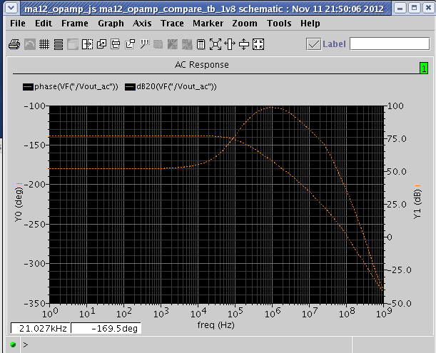
Another method I tried is to simulate with a feedback network consisting of a 100 Gohm resistor and a 10F capacitor to create an output voltage in the middle, but when I do that the phase response starts at -180 degrees.

So... how do you usually simulate open loop? My gain is around 80-90 dB..

Thank you!
 

Jannis,

* the method with a dc voltage at the input that leads to a "good" operating point in the middle of the linear region sounds good and should work - independent on load conditions.
* the other described method is an alternative (with some restrictions due to loading errors) - however what is the purpose of a 100Gohm resistor? Who told you this? Use instead a 100H inductor!
 

I thought that maybe the gain was too high to find a point in the middle . The sweep response looks as I expected but it tilts no matter how close i get to the point in the middle
I also tried with the inductor but the phase response is the same and starts at -180 degrees as seen on the figure. I have never seen anything like that. This only happens when the load is at same potential as the common mode at 2.5 (rail is 0V-5V).


sim.png


I thought that maybe the gain was too high to find a point in the middle . The sweep response looks as I expected but it tilts no matter how close i get to the point in the middle
I also tried with the inductor but the phase response is the same and starts at -180 degrees as seen on the figure. I have never seen anything like that. This only happens when the load is at same potential as the common mode at 2.5 (rail is 0V-5V).

JanniS, your dc response looks as if you are using single supply.
Why don`t you use normal opamp operation with double supply? This will certainly work.
And - select a good resolution for dc sweep (steps of 10µvolts for example).
 

I am not sure what you mean by single supply.

My test bench looks like this:

test.png
 

JanniS, sorry but I don`t completely understand your "test bench".
For example, what is the purpose of the current source ?
Why do you have three inputs ?
At which node is the L-C circuit connected?

Regarding single supply: Are you not aware that in most operations the opamp is used with TWO supply voltages (+-Vsupply) ?
This has the advantage that the input does not need any bias voltages (except a small offset correction in case of missing feedback).
According to your diagram, you operate with one single supply voltage only.
Here are my recommendations:

** Open-loop measurements (normal operation with symmetrical supply voltages):
1.) Inv. input grounded, small dc voltage at the non-inv. input swept over +-5mV (10µV resolution)
2.) Fix the dc voltage at a level which gives approx. zero dc output.
3.) Add an ac source in series to the dc source.
4.) AC analysis gives you gain and phase.

** Alternative (without dc offset correction)
1.) Place a large inductor (100H) between output and the inv. input. Thus, you have full dc feedback (no dc offset problems).
2.) AC analysis with an ac source at the non-inv. input.
3.) For single supply operation of the opamp put the ac source in series to a DC source of 0.5*Vsupply.

Supplement/Correction to point 1.) Place a large capacitor (100F) between inv. input and ground.
 
Last edited:

Status
Not open for further replies.

Part and Inventory Search

Welcome to EDABoard.com

Sponsor

Back
Top