Continue to Site

Welcome to EDAboard.com

Welcome to our site! EDAboard.com is an international Electronics Discussion Forum focused on EDA software, circuits, schematics, books, theory, papers, asic, pld, 8051, DSP, Network, RF, Analog Design, PCB, Service Manuals... and a whole lot more! To participate you need to register. Registration is free. Click here to register now.

Simplest DC 5V power supply design

Status
Not open for further replies.
@godfreyl
Yes, of course.
Hello sir, here are these designs:
Darlington pass transistor regulator Darlington pass transistor regulator.PNG
Basic Series Feedback Regulator Basic Series Feedback Regulator.PNG
Linear Shunt Regulator with active devices Linear Shunt Regulator with active devices.PNG

These are simple design and I want to design anyone of them sir. But I think may be shunt regulator the 3rd one is good among these three. You know better than me, by the way.

@godfreyl and andre_teprom
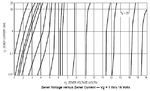
Dear experts! Here is the graph edited picture. I marked what I think by mind not just a chance.
Full-wave rectifier ripple voltage.PNG
I have written 2, does 2 should be there where I have written it? I circled a point with blue in color. Does my capacitor value lay there sir?
Actually, we have never been taught how to read graphs in datasheets or not even datasheets in universities so I am blank from these type of talking. But I will appreciate if you experts make me to understand these things too during this tutorial.
thank you all of you.

PS: sorry for late reply due to my internet connection was disabled.

Regards,
Princess
 

...I circled a point with blue in color. Does my capacitor value lay there sir?

Yes

...we have never been taught how to read graphs in datasheets...

Neither me, anyway...

You must draw mentally a straight line orthogonal to the parallel ones which represents each capacitor scale.
That imaginary line, is logarithmic scaled and you must deduce the grade of the scale that is on.


+++
 
  • Like
Reactions: Eshal

    Eshal

    Points: 2
    Helpful Answer Positive Rating
Your regulator using the darlington has poor voltage regulation because it is missing an error amplifier.
The base-emitter voltage drop of the darlington increases when the load current increases so that is when the output voltage will noticeably drop.

The circuit with two separated transistors has some voltage gain but not enough to make a good regulator.

The shunt regulator will work as poorly as the zener diode in it except the transistor boosts the current.
 
  • Like
Reactions: Eshal

    Eshal

    Points: 2
    Helpful Answer Positive Rating
Why do you want a shunt? A shunt regulator wastes more heat than a series regulator across its operating range.

Whereas on a series regulator the waste heat approaches zero at minimal load and increases fairly linearly with increasing load, on a shunt regulator it wastes maximum power at all loads.
 

@andre_teprom
yes sir, understood. That's why I marked it. Thank you. It helped me through my way.

@schmitt trigger
Why do you want a shunt? A shunt regulator wastes more heat than a series regulator across its operating range.

Whereas on a series regulator the waste heat approaches zero at minimal load and increases fairly linearly with increasing load, on a shunt regulator it wastes maximum power at all loads.
Yes, sir I know this but I thought in parallel path current is divided so heat dissipation will be low but in series current remains same so heat dissipation too. Isn't it? That's why I chose shunt. By the way, I like your name. A schmitt trigger. heheheheheheh.... nice name sir. :p

@Audioguru
Your regulator using the darlington has poor voltage regulation because it is missing an error amplifier.
The base-emitter voltage drop of the darlington increases when the load current increases so that is when the output voltage will noticeably drop.

The circuit with two separated transistors has some voltage gain but not enough to make a good regulator.

The shunt regulator will work as poorly as the zener diode in it except the transistor boosts the current.
I know, my regulator performance is poor. But I still want to design it. I don't want to jump high. I want to be basic through my learning of designing power supply. The simplest power supply. As I succeed in this then I will improve my power supply.

Thank you all for helping such a cutest princess.. hehehehehehe... thnx again experts..
 

...I thought in parallel path current is divided so heat dissipation will be low but in series current remains same so heat dissipation too. Isn't it?...

Shunt regulators require much more power than comparated to series regulators. Working concept on shunt regulators is based on discarding unwanted energy, whereas on series regulator unwanted energy is merely not supplied.


+++
 
  • Like
Reactions: Eshal

    Eshal

    Points: 2
    Helpful Answer Positive Rating
Ohhhh I see sir. That's why series is good than shunt. Now my concept is clear regarding with these two. And you know sir, I also read it in book throughly again.
Now, I want to design series regulator.
 

Hello experts!
I have now unregulated voltage and current are 7v and 1.5A, respectively. And these unregulated specifications are the output of the filter capacitor and serve as the input for the regulator section. And I am going to design series regulator.
Can you experts help me where to start for regulator?
Here is the schematic for the series regulator below,
Basic Series Feedback Regulator.PNG

Thank you.
 

How to start calculating values of R1 and R2? :(
 

First you must select suitable transistors and a low voltage zener diode. A low voltage zener diode has poor voltage regulation.

The minimum current gain (hFE) of Q1 at the maximum current (1.5A) is its base current in the circuit and it is listed on the datasheet for Q1. Then use Ohm's Law and simple arithmetic to calculate the value of R1. use half the calculated value because R1 also provides the current for Q2.

The zener diode has the current of Q2 in it plus the current from R2. The datasheet for the zener diode lists its recommended current, subtract the current of Q2 then again use simple arithmetic to calculate the value of R2.

The datasheet for Q2 lists its minimum current gain at the current it will operate at then you can use simple arithmetic to calculate its base current. Make the current in R3 the pot and R4 10 times the base current of Q2 then again use Ohm's Law and simple arithmetic to calculate their values.
 
  • Like
Reactions: Eshal

    Eshal

    Points: 2
    Helpful Answer Positive Rating
I don't want to jump high. I want to be basic through my learning of designing power supply. The simplest power supply. As I succeed in this then I will improve my power supply.
This is a very good idea.

How to start calculating values of R1 and R2?
Before you calculate any values, you need to understand how the circuit works. Did you figure that out yet?

Can you write a simple explanation of how it works? No fancy formulas, just a simple description.
 
  • Like
Reactions: Eshal

    Eshal

    Points: 2
    Helpful Answer Positive Rating
It's probably a good idea to replace Q1 with a Darlington such as TIP121 or BD677.
 

Ohhhhhh.... thank you so much all of you for help :-* ;-)

@godfreyl
Before you calculate any values, you need to understand how the circuit works. Did you figure that out yet?

Can you write a simple explanation of how it works? No fancy formulas, just a simple description.
Yes, Here it is with schematic below:
Reference voltage is set by zener diode. Q2 detects and then amplifies the difference between the sample voltage and the reference voltage and then adjusts the conduction of the Q1 (pass transistor).
If load resistance increases then load voltage starts to increase. As the voltage divider is in parallel with the load so Q2's base voltage also increases, which increases its conduction and R1. But Vc of Q2 decreases which results in the reduction of base voltages of Q1 and also the conduction through the Q1 also decreases which causes load current to decrease hence it offsets the initial increase in RL
And its opposite is true if load resistance decreases.

Is it right sir? if any mistake then let me know sir.

It's probably a good idea to replace Q1 with a Darlington such as TIP121 or BD677.
Yes sir, I will do it for sure. But after designing this one. After this, I will try to improve my design. Just say, I am a dumb student in electronics you are trying to teach. :)

@andre_teprom and @Audioguru
Dear sirs !! First review my explanation about circuit working then I will start designing.
By the way, why low voltage zener? and how to choose my desired transistor? Are there any specific parameters which should be considered in choosing transistor like diode in which we consider reverse voltage, forward voltage, forward current and its power. So is there any specification with transistor too?

Thank you

Regards,
Cutie Princess :)
 

Yes, that is a good explanation. :grin:
 

By the way, why low voltage zener?
For a 5V output then the zener must be 4V or less ijn your circuit. But a document about zener diodes shows that a 6.5V zener is good, a 6V zener is fair, a 5V zener is not good, a 3.3V zener is bad and a 2.2V zener is horrible. the graph shows the amount the voltage changes when the zener current changes. A good zener shows a vertical line and a resistor that has no voltage regulation shows a slanted line like the poor zener diodes.

how to choose my desired transistor? Are there any specific parameters which should be considered in choosing transistor like diode in which we consider reverse voltage, forward voltage, forward current and its power. So is there any specification with transistor too?
You listed some important spec's but the current gain is also important. A TIP31 power transistor has a minimum current gain of only 22 at a collector current of 1.5A then its base current is very high at 68mA.
A TIP120 darlington power transistor has a current gain of 1000 so its base current is only 1.5mA.

I am glad that you understand how the circuit works.
 

Attachments

  • zener diode VI curves.PNG
    zener diode VI curves.PNG
    32 KB · Views: 66
  • Like
Reactions: Eshal

    Eshal

    Points: 2
    Helpful Answer Positive Rating
Status
Not open for further replies.

Similar threads

Part and Inventory Search

Welcome to EDABoard.com

Sponsor

Back
Top