neazoi
Advanced Member level 6
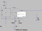
Hi I want to build a simple phase splitter for sine wave for 1-30MHz. If that possible with a single transistor or other discrete transformerless design?
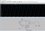
My experiments with simple transistors show that depended on the frequency there are amplitude variations and large phase errors.
My experiments with simple transistors show that depended on the frequency there are amplitude variations and large phase errors.