Continue to Site

Welcome to EDAboard.com

Welcome to our site! EDAboard.com is an international Electronics Discussion Forum focused on EDA software, circuits, schematics, books, theory, papers, asic, pld, 8051, DSP, Network, RF, Analog Design, PCB, Service Manuals... and a whole lot more! To participate you need to register. Registration is free. Click here to register now.

silly question about floating RF to GND or VCC

Status
Not open for further replies.

pgib8

Member level 2
Joined
Aug 9, 2016
Messages
44
Helped
1
Reputation
2
Reaction score
3
Trophy points
1,288
Activity points
1,824
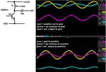
I'm looking at a simple FM transmitter output (see picture). It is from the collector of a transistor and it goes through a DC blocking capacitor before the antenna would be connected. The entire circuit is floating from true ground. I'm thinking of making the antenna a dipole and suddenly I'm stumbled whether to make the other leg the circuit GND or positive rail. The supply voltage is 3VDC and the RF signal is about 1.8Vpp 100MHz. Part of me thinks that the main antenna port will be floating somewhere between GND and VCC. The other part of me thinks that the DC blocking capacitor will be a low impedance at RF so that the RF is actually "pushing against" GND or VCC but I don't know which one. I also know that if I didn't make it a dipole, the one antenna lead would form a capacitor back to the circuit to complete the circuit, again I don't know if it's to GND or VCC, for some reason I just can't wrap my head around this. I thought maybe I measure it with an oscilloscope, I even tried to clip the ground leads from the scope to VCC or GND trying to figure this out but I think the 1M-Ohm probes just pull the RF to one or the other.
I hope someone can help me understand this and I would really appreciate any help.
 

Attachments

  • notsure.png
    notsure.png
    77.9 KB · Views: 91

Very important in getting a good power line decoupling, is the position (where is placed) the decoupling capacitor(s).
In your circuit I would recommend a 1nF capacitor placed at the joint of RF choke and +VDC, and connected to the ground very close to the joint of the Q2 emitter and ground.
To avoid unwanted loops during measurement, also important is where you connect the ground of the scope probe, in this situation should be also near the connection of Q2 emitter to ground.
 

Thanks for the tips. It looks like I got that part right, but don't laugh at my circuit (ok you can laugh at it) :)
The decoupling capacitors are 2x 100nF and 1x 1nF.
1603371437874.png
 

I don't need a ground plane, and it's only 100MHz. Compared to the wavelength this is tiny. I'm more interested how to hook up a dipole from here. Even if I did a balun, I don't know if I would center tap the antenna output and use both VCC and GND or just one of them, or if it even matters.
 

I didn't laugh at your previous post, but now yes ... I have to ... :)
Using your floating flying wires circuit, I think even 100 kHz is a frequency too high.
Build the circuit using a solid ground as I recommend in the above link, and we speak after.
 

The circuit is working perfectly and is very stable. I could add a proper ground plane but the improvement would be so slight, it would not be worth the trouble. Most of my work is in the 902 to 928 ISM band so I have a pretty good feeling of what I can get away with. The key is when the traces are very short compared to the wavelength.
 

I pretty much figured it out I think. In the dipole scenario, the antenna output leg will form a very nice capacitor to the other leg and thus to either VCC or to GND depending on how I connect it. Which is better actually changes throughout the cycle, during one half the RF current needs to go to VCC and during the other half the RF current needs to go to GND. Even though VCC and GND are isolated, they are actually connected together at RF frequencies via the decoupling capacitors. So in the end it doesn't matter which side I pick for the other leg, the current still has a path to either side.
 

Hi
the antenna output leg will form a very nice capacitor to the other leg
To be more clear: It will not "form" a capacitor (by accident or so). There (see schematic) is a physical capacitor designed in.

GND plane.
I'm a friend of GND planes. And I know that not only the wire length matters, but the enclosed area (including the return path), too.
In other words: a "wire" will always act as series impedance (bandwidth limiting). But a properly designed trace over a GND plane (microstrip ...) will not act as series impedance.
I'm not experienced enough in analog HF, thus I can't say how much this influences your circuit.

Klaus
 

Perhaps a phase splitter is adequate? It produces a waveform with opposite-going directions from the incoming waveform. I can't be certaln whether it's correct for broadcasting radio waves.

It's because I still have not seen it explained whether a radio wavelength:
(a) consists of photons spinning one way ('plus') alternating with photons spinning the opposite way ('minus'), or
(b) consists of few photons (trough) alternating with numerous photons (peak).


It's a concept whose counterpart is a similar question: whether a broadcast antenna has true bipolar AC running through it, or fluctuating DC?

I put together an FM transmitter kit containing a few components. Like your circuit it had no ground plane. Powered by a 9V battery. It worked for me although it did not help me to gain insight into the above questions.

From what I understand the goal is to tune your output stage (including antenna) so that standing waves are created. Volt levels rise to a point that causes photons to jump from your antenna.
This can happen even from a power supply of merely a few volts.
--- Updated ---


Phase splitter:
phase splitter NPN pot adjusts bias 3VDC supply.png
 
Last edited:

In a monopole antenna, you have a point of the highest current (usually at the bottom) and a point of highest voltage with no current at the tip. The current basically shoves electrons into the tip of the antenna (i'm just looking at part of the cycle). The bunched up electrons create a electric field. When you think of where the field lines go, where they terminate, in this case that is going to be the ground, whether ground plane on the PCB or radials. The capacitor in my little schematic is not part of this, instead think of another capacitor that is basically the air around the antenna. You want to field lines to have a nice shape and a good path if you want the antenna to radiate well (among other things). Standing waves is normally not what you want because it only happens when there are reflections. Ideally all the energy is radiated into space. When there are reflections they also mess with the amplifier (depending on timing etc.), the amplifier may need to work extra hard not only to produce the power towards the antenna but also to overcome the reflection first (plus other undesirable things can happen).
For a dipole you don't need the ground plane. In a sense a dipole is a complete antenna whereas a monopole is only half an antenna. The electric field will be from one tip of one leg to the other tip on the other leg. Maximum current will be in the center.
A microstip line balances out the series inductance of the trace with the parallel capacitance to the ground place, the two combined are called the characteristic impedance of the transmission line and they are usually dimensioned to be 50 Ohm. This doesn't mean 50 Ohm per inch or anything like that but regardless of the length 50 ohms. The transmission line could be 1 inch long and terminated with a 50 ohm resistor, or it could be 1 mile long and terminated with a 50 ohm resistor, or technically it could be infinitely long and not terminated at all. The amplifier or whatever that is "looking" into this transmission line will just see 50 ohm in each case. Even a wire can be dimensioned like this. Actually you should look up TEM cell. It's a transmission line that is blown up so you can put circuit boards inside, some you could walk into them they are so big but still come together as 50 ohm. I don't have experience with phase splitters but in essence that's how you feed a dipole. When one is positive the other is negative, just like you showed in the picture. By far the easiest way people do this is by making one leg go through 1/2 wavelength extra transmission line, to delay the signal by 180 degrees compared to the other leg. If there is a small imbalance between the 2 legs of the dipole, ex. one goes to 2V at the same time the other one goes to -1.9V, then I suppose a small portion of that electric field needs to find another path and you can think of it as capacitors going everywhere, even up into the air. So if it can't use the wire itself for the imbalance (ex. if there is a choke), then it just forms a little extra field with the earth itself and then on the transmitter side the same thing happens. But for the most part if the antenna is half ways decent then you don't have to worry about this, and no antenna is going to be perfect either. As far as impedance matching goes, if you want the maximum power transfer you have to match the conjugate impedance, the real part needs to be the same and the imaginary part needs to cancel out. Maximum power transfer is not always the goal, I think impedance matching for best signal is another story and I believe people may do this with speakers but I don't know much about that.
 
Status
Not open for further replies.

Part and Inventory Search

Welcome to EDABoard.com

Sponsor

Back
Top