Continue to Site

Welcome to EDAboard.com

Welcome to our site! EDAboard.com is an international Electronics Discussion Forum focused on EDA software, circuits, schematics, books, theory, papers, asic, pld, 8051, DSP, Network, RF, Analog Design, PCB, Service Manuals... and a whole lot more! To participate you need to register. Registration is free. Click here to register now.

Signal separator for analog output

Status
Not open for further replies.

MtzJhNO

Newbie level 3
Joined
Jul 24, 2016
Messages
4
Helped
0
Reputation
0
Reaction score
0
Trophy points
1
Activity points
76
Hi. I have a DAC board (for a raspberry PI) that uses a MCP4812 for analog outputs (board diagram: https://www.horter.de/doku/i2c-hs-analog-output_sp.pdf) The outputs of the DAC are used to controls the 0-10v input of a Meanwell LCM LED driver (for controlling LED downlights in my house). FYI, the connection schema looks like this:
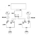
schema.JPG

Now, sometimes a glitch appears in which the channels of the DAC are magically (re)set to 0v. This happens for ex. when first driver1/LED1 is turned on. Output of CH0 is set to 100% (all good, LED is at max light value). Next driver2/LED2 connected to CH1 is turned on. When doing so the other channels of the DAC (CH0,2,3) are now (re)set to 0V. Meaning that LED1 which was previously at 100% suddenly drops to its minimum. To make things worse, this happens 'randomly' like 2 out of 10. After replacing and testing almost everything I found out that it must be the driver which is disrupting the output of the other channels of the DAC through it's "0-10v connection" from the moment it is turned on. When the 0-10v is disconnected of the driver that is toggled the outputs remain at their configured value.

To test this theory I was thinking on try placing a signal repeater that has galvanic separation between the DAC output and the LCM. It would then 'copy' the 0-10v signal from the DAC ouput to the driver input. However, the best I can come up with is a Wago 857-412. This is a rather expensive solution to a) test a theory b) even if it works I need one for each channel.

So, my question is, is there perhaps a cheaper solution for such a separator? Other ideas on how to tackle this are more than welcome.

Thanks for reading.
 

I presume you have checked that the problem is caused by electrical noise (e.g. when switching power relays) rather than programming faults.

If so, I2C and DAC board power supply wiring can be expected to be the critical point. An I2C isolator IC (e.g. offered by TI) together with separate power supply is surely cheaper than analog isolators. Common mode chokes for digital and analog interfaces in combination with better power supply bypassing might be sufficient to get rid of the problem, also RC snubbers for power relay contacts.
 

I presume you have checked that the problem is caused by electrical noise (e.g. when switching power relays) rather than programming faults.

Hi. Yes, software faults have been ruled out. The only software in place is a test program that first turns on driver1 (via KNX) and sets CH0 to 100% (via I2C). Next it starts toggling driver2 (via KNX) with a 500ms interval in an endless loop. The relais is a KNX actor and is thus elektrically completely separated from the RPI setup. It is however controlled from the same test program running on the RPI, but this has no impact (eg. removing this code and toggling the relais manually yields the same problem).

Also, the glitch (that CH0 is automatically reset) appears randomly, but 90% of the time between "1 and 20 times of toggling" driver2. This test has now been executed many (many) times and it is consistent in that respect. From the moment the 0-10v of driver2 is disconnected from the DAC the glitch dissapears, from the moment it is connected again, the glich re-appears. This is also consistent.

If so, I2C and DAC board power supply wiring can be expected to be the critical point. An I2C isolator IC (e.g. offered by TI) together with separate power supply is surely cheaper than analog isolators. Common mode chokes for digital and analog interfaces in combination with better power supply bypassing might be sufficient to get rid of the problem, also RC snubbers for power relay contacts.

True, this might have some impact. Right now the DAC is connected to an RPI2 via i2c running over an 8 meter long (non shielded, non twisted) cable connection. The power of the DAC also runs via this cable and comes from the RPI (RPI and DAC share same power supply). This is rather long, but as there is a repeater in place (**broken link removed**), since the DAC requires 5v levels, and I'm not experiencing any other problems I thought this would be fine. To rule this out I already tested by connecting another RPI (model3) directly next to the DAC (i2c connection like 10cm). In this setup the RPI and DAC still shared the same PS however. It has to be said that the glitch now only appeared very very seldom, but it was still there. Let me first try with a separate PS for both RPI and DAC. Thanks.
 

Referring to the schematic linked in post #1. If it's true that three tiny 100 nF capacitors are the only supply filter and bypassing means on the interface board, I would conclude that it's not designed for longer cables than a few 10 cm, respectively any electrically "noisy" environment. A spontaneous µP or DAC reset can likely happen in response to power supply spikes.
 

Referring to the schematic linked in post #1. If it's true that three tiny 100 nF capacitors are the only supply filter and bypassing means on the interface board, I would conclude that it's not designed for longer cables than a few 10 cm, respectively any electrically "noisy" environment. A spontaneous µP or DAC reset can likely happen in response to power supply spikes.

Yes, BUT, the weird thing is that I already tried to separate the RPI power supply and DAC output power supply from the power grid. What I did is power the RPI via USB on my laptop (and thus not via the normal DIN rail 230VAC PS) I then powered the DAC output channels via a 18VDC drilling machine battery :) also, my laptop was running on its batteries during the test :) Not the most high tech setup, but still, this would elektrically separate RPI/Repeater/DAC PIC and DAC output from the power grid and thus shielding it from possible spikes when turning on/off drivers. Still, the exact same problem persists.

Since the glitch ONLY appears when toggling a driver, I'm 99.9% certain that this 0-10v "input" on the LCM is somehow "sending" a disruptive signal to the DAC output. Could this be possible that a signal can influence the DAC based on the schematic of the board? I already tried short circuiting the DAC outputs but I couldn't simulate it (they all remained at their configured output level). So this makes me believe it is a real instruction that is send to the DAC (like a reset or something) but how could this be possible via the output? Is there perhaps another way of making sure that no "signals" from the LCM are sent to the DAC output?
 

Just noticed that the DAC board schematic is incomplete, not showing where the 12V supply is originated from. So there's little use in guessing about possible unwanted effects.

I primarily thought about crosstalk from the 230V side, particularly relay contact arcing. If "noise generating" actions are involves with controlling the DAC and resets happen though, there might be in fact an internal problem of the DAC board. But did you cross check by e.g. shorting the cables, operating the light controllers without load etc.?

Fast spikes can be picked up by a cable of some length, you don't need a direct mains connection.

Btw; the 12v supply for the DAC output is leveraged by a second power supply. In my case it's a DIN rail mounted meanwell 12v DC PS. Apparently the LM allows to use a voltage up to 24v DC (in my test setup this PS was replaced by the 18v DC battery). Anyway, I burned my repeater in the meantime, so I have to get a new one first before I can re-test some scenario's.

That said, the spike theory is interesting. But the weird thing is that it only happens when the DAC output is connected to the driver input that I'm toggling. When it's not connected the driver goes automatically to 100% when turned on, so there is the exact amount of load as with the DAC connected but there are no problems with other drivers (which are off course still connected to the DAC). If it would really be due to spikes in the power supply of the RPI/DAC caused by toggling a driver then it should also happen without the DAC being connected to that driver. Unless the spikes are propagated through the 0-10v "input" to the DAC output.

Anyway, electrically decoupling the DAC output from the driver input is the only part of the puzzle I didn't test as I don't know how (besides getting an expensive Wago seperator). So if there is any other way to do this then I would be glad to hear about it:)
 

Status
Not open for further replies.

Similar threads

Part and Inventory Search

Welcome to EDABoard.com

Sponsor

Back
Top