zizi110
Member level 1

- Joined
- Jun 24, 2013
- Messages
- 41
- Helped
- 0
- Reputation
- 0
- Reaction score
- 0
- Trophy points
- 6
- Activity points
- 313
Hi all,
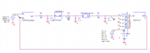
i am trying to design a sigma delta modulator in pspice by ABM library , here it is my schematic , nut it dont work!
first block subtract the input from output , then the result goes to integrator and then if the result is positive the output becomes 5 , else the output becomes zero and this output goes to 74175 that its clock rate is 10kHz ..... however this circuit does not work!
any suggestion appreciated.