Continue to Site

Welcome to EDAboard.com

Welcome to our site! EDAboard.com is an international Electronics Discussion Forum focused on EDA software, circuits, schematics, books, theory, papers, asic, pld, 8051, DSP, Network, RF, Analog Design, PCB, Service Manuals... and a whole lot more! To participate you need to register. Registration is free. Click here to register now.

Short version of help for the ICD2

Status
Not open for further replies.
ft232+icd2

the clock supply is not required for programming, but it is req. for debugging. the target board has to be functional for debugging

for the differences read the datasheet - if both of them have same logic levels (input and otput) and same speed, than there is no significant difference.

0x41 0x56 0x45!!
 

icd2+ft232

Hello to all
Beginner here and I would like to know why the firmware (www.icd2clone.com) is not working!
I constructs PiCS (Rev C)
Someone did work?
I thank your help

Felipe - Brazil ... Google translate
 

ft232 icd2

Hi there,

The suppled firmware posted at the top of this thread is definitely working for Potyo's version of the ICD2. I cannot vouch for the Pics version as I did not build it. Maybe someone else with PICS experience can help out here.

All the stuff I have posted in this thread is tested aqnd worked for me with Potyo's version of the ICD2. As I said I do not guarantee that everything is the latest version but it works for me. If it does not work, go and search the main thread please.

Regards

Nic

Added after 3 hours 28 minutes:

Another document that can be of good use to you for getting the ICD2 running:

**broken link removed**

It shows you how to install the correct drivers for windows to use.
 

mc34063a en eagle

I've made the PICS rev.B ICD2 Clone, but i've encountered a problem...
After connecting the ICD2 to the USB port, it works fine for a couple of minutes(It works in MPLAB, and it programs MCUs without any problems), than it shuts down... The USB-LED turns off (D5 on the schematics), but the POWER-LED is still on. Only thing i have to do, is touch (not even touch, just pass my hand over it) the MCUs on the ICD2 Clone, and it comes back on.

What can be the problem here?
It seens to me like a capatitance-issue...
I've replaced L1 with just a piece of wire, and tought this could be a problem. I soldered on an inductor, but the same problem occurs.

Can anyone help me with this?
 

icd2 zip socket

Never mind, I figured it out... I removed MCLR from the firmware for the 4550 MCU, and now it works like a charm :D
 

potyo icd2 firmware

I think people should discuss continuously about this topic
It is interesting.
 

potyo icd2 overwrite problem

I've built ICD2 version of Lothar Stolz. It's working with MPLAB 7.60a. The speed however is limited to 57600 Baud Rate. For programming it's enough, but for debugging it's far too slow. Anyway, whoever wants to make one, here are all the files (schematics, pcb, hex). I've collected some similar clones from various other sites so you can choose which one to make. Originally all they come from Lothar Stolz design.
**broken link removed**
 

icd2 pics (rev c)

I don't manage to connect an pic 16f873 with an IDC2 clone build after poyo's schematics.Where did I go wrong : the project https://www.hobbielektronika.hu/kapcsolasok/usb_icd2.html?pg=4&Submit=>> and i connected the pic's pins :
pic pin 1 to potyo's ISP-MCLR - 6
pic pin 28 to potyo's ISP-PGD - 3
pic pin 27 to potyo's ISP-PGC - 2
pic pin 19 to potyo's GND - 4
pic pin 20 to potyo's ISP-VDD - 5

Please a little help is needed...

Thank you in advance.
 

dgs117 said:
I've built ICD2 version of Lothar Stolz. It's working with MPLAB 7.60a. The speed however is limited to 57600 Baud Rate. For programming it's enough, but for debugging it's far too slow. Anyway, whoever wants to make one, here are all the files (schematics, pcb, hex). I've collected some similar clones from various other sites so you can choose which one to make. Originally all they come from Lothar Stolz design.
**broken link removed**

My Inchworm design is based on the Stolz design, I've simplified the HV generation and it requires only common parts.

I'm even selling off the remaining 50 Original Inchworm PCBs cheap.
**broken link removed**
 

Thanks for ... you're attention :D I manage to solve the problem...
 

for dgs117,
ICD2 version of Lothar Stolz uses a FT232BM to emulate an USB port, but it isn't one. FT232 firmware creates a COM port to comunicate with MPLAB. That's why velocity is limited to 57Kbps. Really it is a COM port and not an USB.
So, version of Lothar Stolz is really a serial ICD2.
 

Yes, I know that, but it's a good starting point for building a more advanced ICD2 with full USB support. I use it only for programming, so it satisfies my needs for now.

cherreram said:
for dgs117,
ICD2 version of Lothar Stolz uses a FT232BM to emulate an USB port, but it isn't one. FT232 firmware creates a COM port to comunicate with MPLAB. That's why velocity is limited to 57Kbps. Really it is a COM port and not an USB.
So, version of Lothar Stolz is really a serial ICD2.
 

Tested firmwares

Because i'm bored and when i'm bored i do stupid things... i'm going to test in my PICS (b) ICD2 clone, the 3 firmwares that are supplied in this thread. No problem, it's not the first time i used it for experiments... and i still am alive :D

I will comment my results later...

Added after 2 hours 30 minutes:

I have tested the firmwares for PICS clone using 877A instead 877. They work well.


A question, the 2nd firmware for 4550... where is? i suppose that modifications are included in the 3rd.
 

Hello, I am new in this forum, and this is my first post (and my english could not to be the best, so sorry).

2 weeks ago I started the ICD2 Clone (based on potyo2-rev1, zip).
I made the pcb, and soldered all the components, placed the jumper near the 4066.
So I conected this to the computer, installed the drivers, download the SO, and conected in MPLab (8.10). All works very well.

But some days ago I do one pcb to program pic 16F628A, for test of the icd2 clone.
But for my surprise it does not work (write). I can conect, but I can't write/read the 'device'. And whatever I do the MPLab always show:

Connecting to MPLAB ICD 2
...Connected
Setting Vdd source to MPLAB ICD 2
ICDWarn0020: Invalid target device id (expected=0x83, read=0x0)
...Reading ICD Product ID
Running ICD Self Test
...Passed
MPLAB ICD 2 Ready

The problem is:
ICDWarn0020: Invalid target device id (expected=0x83, read=0x0)


I don't know what to do. I revised the conector, the solder, the cable. I change the pic (anothers 16F628A, and some olds 16f84A) and always I have the same problem.

Anybody can help me? please

Thanks for all.

Mario Sbampato - São Paulo / Brazil

Added after 4 minutes:

OBS: The ics are not EXACTLY the same. I used:

CD4066
74126N
SN74LS125AN
SN74LS07N

I don't think that the problem is these ICs.
 

Hi sbampa12, did you select the correct pic in maplab? You go to the menu: Configure->select device-> (and then select the pic you are trying to connect)

regards
 

Old poster but it may shed some light on your first MPLAB program
**broken link removed**
You can download the hires PDF version from my site in the downloads section.
 

The one use of ICD2 :)

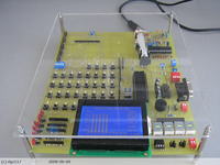
I made my own dev board for PIC18F4520. It's more or less like EasyPIC4. There is an on-board MPLAB 7.60a compatible ICD2 (upper right corner). Yesterday I demonstrated this board as my final work for bachelor's degree. It works but still needs a lot of improvements. The board features a lot of perphereals, like I2C (for eeprom), SPI (for MAX7219), OneWire (for DS1820), RS232 (MAX232), analog input (two potentiometers), socket for resonator, piezo buzzer, two connectors for LCD 2x16 and GLCD 128x64, pull-up/down resistors, push buttons, LED's, each port has a connector for external devices. Each device can be connected/disconnected with a dip switch or a jumper (like in EasyPIC's).

I could publish the schematics and all but I wont, coz the design is not perfect yet. It will be (I hope) after summer :)


Can any body send me the snapshot of MPLAB ICD2 Debugging.
you only need to just debug the Assembly code of LED On/OFF program.
And take a snapshot by pressing Printsys button and paste in paint and send me.

I want to see.
thanx

Added after 1 minutes:

Debugging shows every thing like Register, Assembly code , memory, disassembly etc.
 

To Blueroom,
I tried making your Inchworm+, and the device passes the self-test and connects through MPLAB (7.60) however, when it says "Device ID error, expected =0x1C1, value read = 0xE1" when i try to download operating system for dsPIC 30F4011. I used MAX 232 (ST232 is not available anywhere) with 10uF caps, could this be the reason ?
 

Status
Not open for further replies.

Part and Inventory Search

Welcome to EDABoard.com

Sponsor

Back
Top