Welcome to our site! EDAboard.com is an international Electronics Discussion Forum focused on EDA software, circuits, schematics, books, theory, papers, asic, pld, 8051, DSP, Network, RF, Analog Design, PCB, Service Manuals... and a whole lot more! To participate you need to register. Registration is free. Click here to register now.
I understand how to implement shift register (serial in parallel out) in verilog on data bits. But I would like to implement it on a word data. Could anybody guide me?
I don't understand your question. A word is just a bunch of bits. What don't you understand? Maybe give us an explanation of what you're trying to do. Are you trying to shift words (e.g., 16 bits at a time)? What's your output width then?
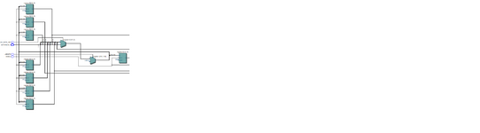
Sorry guys for not making my question clear. I just wanted a 2D array shifting mechanism in verilog. More like a word length shift register. I could find from the resources available on the internet. Strangely I get two different synthesis results on the following code. RTL viewer images are attached
code 1:
Code:
reg [0:15] register[0:8]; //2D array
integer i;

always@(posedge SYSCLK)
begin
if(RESET==0)
begin

  register[0] <= 16'd0;
  register[1] <= 16'd0;
  register[2] <= 16'd0;
  register[3] <= 16'd0;
  register[4] <= 16'd0;
  register[5] <= 16'd0;
  register[6] <= 16'd0;
  register[7] <= 16'd0;
  register[8] <= 16'd0;


end

else if (ADC_DATA_RDY==1)
begin
       for(i = 8; i > 0; i=i-1) begin
          register <= register[i-1];
       end
       register[0] <= DATAIN;
    end
end
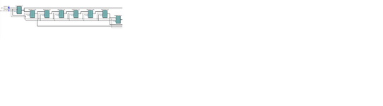
Code 2: Reset is removed
Code:
if (ADC_DATA_RDY==1)
begin
       for(i = 8; i > 0; i=i-1) begin
          register <= register[i-1];
       end
       register[0] <= DATAIN;
    end
end
I want the logic as intended in code2. Why does Code1 not synthesize the way of code2?
Not exactly. The OP implemented a (syntactically correct) synchronous reset, possibly unintentionally. This is also the reason for the different look in RTL viewer.
The usual implementation would be an asynchronous reset
This site uses cookies to help personalise content, tailor your experience and to keep you logged in if you register.
By continuing to use this site, you are consenting to our use of cookies.