Continue to Site

Welcome to EDAboard.com

Welcome to our site! EDAboard.com is an international Electronics Discussion Forum focused on EDA software, circuits, schematics, books, theory, papers, asic, pld, 8051, DSP, Network, RF, Analog Design, PCB, Service Manuals... and a whole lot more! To participate you need to register. Registration is free. Click here to register now.

Shape of Differential Mode Transient Waveform from Opamp?

Status
Not open for further replies.

ehsanaiman

Junior Member level 2
Joined
Sep 17, 2017
Messages
22
Helped
0
Reputation
0
Reaction score
0
Trophy points
1
Location
Batu Pahat
Activity points
185
Hello,

Im doing schematic and simulation of opamp circuit using Synopsys Hspice 90nm technology, . For input, Im using 8mV, 500Hz as V+ input (AC 1V and 0 deg phase) and -8mV, 500Hz as V- input (AC 1V and 180 deg phase). So after transient, DC and AC simulation, the gain obtained is correct according to the value of Vpeaktopeak which is 55.1dB, but the shape of transient waveform is wrong (not in sinusoidal shape, refer the picture attached. What is the cause of that phenomenon?
I think that shape is not cause by signal clipping because the gain calculated from Vpp output and Vpp input equal to 55.1dB which is gain of that circuit.
I also attached the schematic diagram of opamp and feedback circuit for reference.
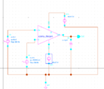
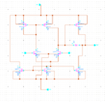
circuit2source.PNGcircuit.PNGtransdiff.PNG

Thank you.
 

Hi,

I assume it is clipped.... as usual for a non feedbacked OPAMP.

to 55.1dB which is gain of that circuit.
Where do you have this information from?

Klaus
 

Hi, thank you for the reply.

The Vdd and Vss is 0.5 V and -0.5V respectively. What you meant by non-feedbacked OPAMP? Is there any criteria for OPAMP to be stated as feedbacked OPAMP?
As for the gain, I have simulated the circuit and refer to the images attached, that is gain from the circuit.

transdiff.PNGacdiffgain.PNG
 

Hi,

Usually an OPAMP uses feedback to set it´s gain.

Still unclear where your 55.1dB come from.
At 500Hz I see about 32dB ... surely not 55.1dB
To me it seems as if your dB values is from your "clipped" simulation. But a clipped signal is not useful for a gain calculation.

Btw: usually speaking about 8mV AC means 8mV RMS .. but in your case single ended input is 8mVp = 16mVpp = 5.7mV RMS.
So the differential input is +/-16mVp = 32mVpp.

Klaus
 

I presume the calculated gain is the result of small signal AC analysis.

1. According to acdiffgain.png, the gain at 500 Hz is lower than 55 dB, may be 52 dB.
2. A gain of 52 dB would result in 6.4 Vpk output with 16 mVpk differential input.
3. Power supply of +/- 0.5V limits the output voltage to 0.5Vpk. That's what we call "clipping".
 

Hi,

At 500Hz I see about 32dB ... surely not 55.1dB
Wrong. I was looking at 5000Hz.

FvM gave the correct values.

Klaus
 

Hello FvM, thank you for your answer.

I understand that power supply +/- 0.5Vpk will clip the output signals.
So, if i increase the power supply into 10Vpk, the output signal would not be clipped again right?
and in my case, I need to use the +/- 0.5V as Im looking to reduce the power consumption of opamp in my research, so is there any other way to reduce the gain of opamp?

Thank you.
 

Hello KlausST,

Im doing research regarding ECG signals where the signal of real ECG difficult to be simulated, so I subsituted it with 8mVp with 500Hz.
If I changed the type of 8mVpk to 8mV AC, then the gain signal will be clipped again or not?

Thank you.

- - - Updated - - -

Hello KlausST,

Im doing research regarding ECG signals where the signal of real ECG difficult to be simulated, so I subsituted it with 8mVp with 500Hz.
If I changed the type of 8mVpk to 8mV AC, then the gain signal will be clipped again or not?

Thank you.
 

Hi,
If I changed the type of 8mVpk to 8mV AC, then the gain signal will be clipped again or not?
Why do you ask us? Why don't you use your simulation tool?

Klaus
 

Hi KlausST,

Ive already do the simulation and I cant get the simulation results as before but nevermind.
I also have some questions regarding the values of TOX and VTHO where I am using BSIM4 level 54 model and it is stated that TOX is equal to 3.0e-9m and VTHO is equal to 0.7V, meanwhile values of TOX and VTHO from parameter file of SAED90 stated that TOX is 2.05e-9 and VTHO is 0.397.
Which value is right to use in calculation of determining W/L ratio in amplifier?

ehsanaiman
 

Status
Not open for further replies.

Similar threads

Part and Inventory Search

Welcome to EDABoard.com

Sponsor

Back
Top