s.manikandan
Member level 3

- Joined
- Nov 30, 2011
- Messages
- 55
- Helped
- 1
- Reputation
- 2
- Reaction score
- 1
- Trophy points
- 1,288
- Activity points
- 1,759
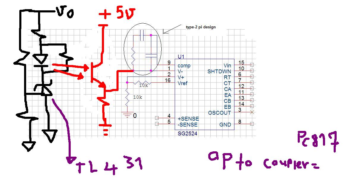
Actually there is '-' ,'+', and comp terminals for sg3524 pwm controller.. i m designing isolated converter for our application. i need to isolate the voltage sensing which is given to '-' terminal of the error amplifier.. how to acheive it..? any idea or example circuit..?
Usually i used to go with tl431 and optocoupler at the feedback side to flow current into the error amplifier to control pwm..
but how to achieve in sg3524 isolated feedback....?
Usually i used to go with tl431 and optocoupler at the feedback side to flow current into the error amplifier to control pwm..
but how to achieve in sg3524 isolated feedback....?