mustangyhz
Member level 5

Follow along with the video below to see how to install our site as a web app on your home screen.
Note: This feature may not be available in some browsers.


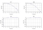
the S11 in the first way is not equal to the S11 in the second way.
why?


I set the port impedance of port 3 and 4 to 0.001
but both models are not the same.

Why not connect these ports to ground (schematic symbol GND)?
Port resistance cann't be set to zero in momentum.
- - - Updated - - -
My purpose:
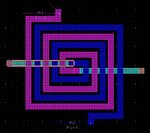
draw the layout of a transformer in cadence => export the gds file => import the gds file in ads momentum => simulate the transformer in momentum => get the S parameters => built a S4P data item => simulate the data item to get the same S parameters => extract the equivalent circuit model parameter of the transformer based on these S parameters => simulate a transformer based circuit in cadence with the equivalent circui model.
I need a four port transformer, so I can not just connect two port to ground when I simulated the transformer in momentum.

Why not connect these ports to ground (schematic symbol GND)?
Port resistance cann't be set to zero in momentum.
My purpose:
draw the layout of a transformer in cadence => export the gds file => import the gds file in ads momentum => simulate the transformer in momentum => get the S parameters => built a S4P data item => simulate the data item to get the same S parameters => extract the equivalent circuit model parameter of the transformer based on these S parameters => simulate a transformer based circuit in cadence with the equivalent circui model.


I know. I suggested to connect two ports of the 4-port EM model to ground at schematic level, so that you have 2-port results which you can compare to the 2-port EM results.
reply:I tried in this way. The difference is too big for me.
for: "For example, S11=0dB at low frequency indicates that you have simulated with lossless metal. "
reply:my substrate file:
VERSION 100
UNIT um
SUBNAME
TOP 0 0 0 0
BOTTOM 0 4 0 0
SUB0 FreeSpace 1 1 0 1 1 0 -1 0.0003115 0.0003115 1 0 0
SUB1 pass 1 7.9 0 1 1 0 0.7 0.0003108 0.0003115 1 0 3
SUB2 OXIDE1 1 4 0 1 1 0 3 0.0003078 0.0003108 1 0 3
SUB3 OXIDE2 1 4 0 1 1 0 0.8 0.000307 0.0003078 2 1 3
SUB4 OXIDE3 1 4 0 1 1 0 3.5 0.0003035 0.000307 2 1 3
SUB5 OXIDE4 1 4 0 1 1 0 3.5 0.0003 0.0003035 2 1 3
SUB6 SUBSTRATE 1 11.9 0 1 1 0 300 0 0.0003 1 1 3
MET1 layer34 0.0003035 0 4 1 0 0 Siemens/m Siemens/m 2 0 um
MET2 layer81 0.000307 2 2 3 2.8e+007 0 Siemens/m Siemens/m 0 2 um
MET3 layer53 0.0003078 1 2 3 2.8e+007 0 Siemens/m Siemens/m 0 2 um
MET4 layer42 0.000307 0 4 1 0 0 Siemens/m Siemens/m 2 0 um
MET5 layer36 0.0003078 0 4 1 0 0 Siemens/m Siemens/m 2 0 um
MET6 layer46 0.0003035 3 2 3 2.8e+007 0 Siemens/m Siemens/m 0 2 um
MET7 layer30 0.0003 0 4 1 0 0 Siemens/m Siemens/m 2 0 um
we can see that layer81, 53, 46 are all not lossless metal. I just used lossless via.
thanks!
- - - Updated - - -
I was not able to import your project to ADS 2011, so maybe you can post pic of momentum results, schematics you used and the schematic simulation results.
you can build a project in ADS 2011 with the attachments including the gds files(two ports transformer and four ports transformer), streammap file(necessary for gds importing) and substrate file(to define the substrate, metals and vias).
thanks!

for: "For example, S11=0dB at low frequency indicates that you have simulated with lossless metal. "
we can see that layer81, 53, 46 are all not lossless metal. I just used lossless via.
