Continue to Site

Welcome to EDAboard.com

Welcome to our site! EDAboard.com is an international Electronics Discussion Forum focused on EDA software, circuits, schematics, books, theory, papers, asic, pld, 8051, DSP, Network, RF, Analog Design, PCB, Service Manuals... and a whole lot more! To participate you need to register. Registration is free. Click here to register now.

Setup to test a filter

Status
Not open for further replies.

atferrari

Full Member level 4
Joined
Jun 29, 2004
Messages
237
Helped
7
Reputation
14
Reaction score
3
Trophy points
1,298
Location
Buenos Aires - Argentina
Activity points
1,996
I have never done this before.

Today I started to test the state variable filter in the attached circuit.

My setup is just a (brand new) function generator sweeping from 30 Hz up to 30 KHz, 1 V pk-pk - 0 offset. Output impedance set to 50 ohms and signal applied to R7 which not yet connected to the preamp.

Soon I realized that I needed to trigger the scope (generator's 2nd channel, delivering pulse with the same period of the sweeping).

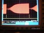
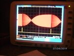
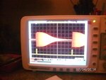
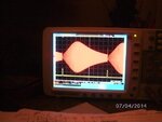
Basically I get a response that barely looks what I could expect for HP, BP and LP (albeit irregular and asymetric) but I cannot find anything that I could call a notch.

Op amps polarization checks as +4,4V, in case you ask.

Eventually I could take some pictures tomorrow.

My questions: am I doing right?

How to measure fc? I suspect there is an obvious way but I cannot think of any right now. I have no markers available.

Comments and suggestions will be aprreciated.
 

Attachments

  • Directional microphone.pdf
    23 KB · Views: 120

R7 is not an input. The microphone is the input and the gain of the preamp is 178 times so you want an input that is about 6mV p-p.

Isn't its sweep range of the function generator logarithmic instead of linear? A plot of frequency response is always logarithmic.
Doesn't your function generator have a logarithmic ramp output to feed the horizontal 'scope input?

fc is simply the frequencies where the response is down -3dB (0.707 times the maximum amplitude).
 

It appears that what you require an audio spectrum analyzer to plot the filter response.

Is that correct?

And indeed, as A.G. mentioned, your scope's other channel is not triggered but ramped with an analog ramp. The scope must thus be in XY mode.
 

R7 is not an input. The microphone is the input and the gain of the preamp is 178 times so you want an input that is about 6mV p-p.

Isn't its sweep range of the function generator logarithmic instead of linear? A plot of frequency response is always logarithmic.
Doesn't your function generator have a logarithmic ramp output to feed the horizontal 'scope input?

fc is simply the frequencies where the response is down -3dB (0.707 times the maximum amplitude).

Yes AG.

I should have said R8 the input to the filter. (Had in mind an old version which I used wrongly for reference).

I am using the logarithimic sweep. Have to check the ramp. Doubt there is any logarithmic...

- - - Updated - - -

And indeed, as A.G. mentioned, your scope's other channel is not triggered but ramped with an analog ramp. The scope must thus be in XY mode.

The 2nd input gets a pulse that triggers the scope's sweep. That makes the trace of the filter's output, stable enough.
 

Since your input is to R8 then IT MUST BE CAPACITOR-COUPLED so that the opamps are not rectifiers.

Sweep frequencies are always logarithmic so prevent high frequencies being crammed together and to prevent low frequencies from being spread apart.
If the sweep frequencies are logarithmic then the horizontal ramp for the 'scope also must be logarithmic, from the same ramp that drives the VCO.
 
Hola AG

After a long time trying, I learnt that my DSO has a strange way of changing settings, even if I do not use the autoset mode.

The circuit is assembled in a very cramped perfboard. Maybe there is something wrong that I am not seeing.

This morning I assembled the same circuit in a protoboard :shock:, brought back in service my old and friendly analog scope and enabled the generator's sync output.

Also made sure to be coupled by a cap. Non-polarized 5uF.

The notch is there, as we use to say, "big as a house" together with other expected outputs.

Being my first time with this, I feel happy. :grin: :razz:

Gracias for replying.
 

Attachments

  • Fotos universal filter.pdf
    87 KB · Views: 113
Last edited:

The frequency responses of your filters look wrong because their frequencies are not made or not shown logarithmically.

Your filters are simple second-order which reduces the output exactly 12dB per octave which produces an absolutely straight line when the frequencies are logarithmic but yours is have curved lines.

Gracias again AG

It is evident there are many things I ignore. I knew that!

Could you make a complete abstract with all the conditions to make a sweep test, including all your remarks and eventually what was not told yet?
 

Could you make a complete abstract with all the conditions to make a sweep test, including all your remarks and eventually what was not told yet?
You are trying to use a function generator then modify it to be a sweep generator.
It will rarely be used as a sweep generator so buy or rent one.
 

There is something additional, which you have to be aware of digital scopes.

If you set a timebase long enough to accommodate -let's say- a sweep 1/2 second long, then your higher frequencies will suffer alias distortion. That is the reason you may see a "correct" response in an analog scope, and weird results in a digital one.

Better ($$$$) digital scopes have gigantic memories to accommodate very long record lengths and avoid aliasing even with slow timebases.
 

Now that I know that my circuit works, albeit the questionable image in the scope I will go back to my DSO and see what could be wrong (me or him).
 
Last edited:

There is something additional, which you have to be aware of digital scopes.

If you set a timebase long enough to accommodate -let's say- a sweep 1/2 second long, then your higher frequencies will suffer alias distortion. That is the reason you may see a "correct" response in an analog scope, and weird results in a digital one.

Better ($$$$) digital scopes have gigantic memories to accommodate very long record lengths and avoid aliasing even with slow timebases.

Went back to the DSO with the circuit still in the protoboard.

No artifacts at all. Here, sweeping period 200 msec but even up to 2 sec period, gave same results.

Regarding my original enquiry I concluded that my circuit should have something wrong.
 

Attachments

  • SANY5546.JPG
    SANY5546.JPG
    51.9 KB · Views: 65
  • SANY5548.JPG
    SANY5548.JPG
    46.6 KB · Views: 84
  • SANY5549.JPG
    SANY5549.JPG
    48.8 KB · Views: 76
  • SANY5550.JPG
    SANY5550.JPG
    37.1 KB · Views: 71

Status
Not open for further replies.

Similar threads

Part and Inventory Search

Welcome to EDABoard.com

Sponsor

Back
Top