Continue to Site

Welcome to EDAboard.com

Welcome to our site! EDAboard.com is an international Electronics Discussion Forum focused on EDA software, circuits, schematics, books, theory, papers, asic, pld, 8051, DSP, Network, RF, Analog Design, PCB, Service Manuals... and a whole lot more! To participate you need to register. Registration is free. Click here to register now.

Series pass regulator question

Status
Not open for further replies.

obrien135

Full Member level 5
Full Member level 5
Joined
Nov 10, 2009
Messages
240
Helped
5
Reputation
10
Reaction score
5
Trophy points
1,298
Location
Connecticut
Activity points
3,259
I built a DC 12V regulated supply using a series pass regulator. I couldn't get a clean DC unless I reduce the output to 12V. I was originally aiming for 17VDC out. The step down transformer had about a 13VRMS output. 13.6V if I remember correctly. So the unfiltered rectified voltage was just under 19VDC. Should I expect less voltage difference between output and input of regulator? Maybe I don't have enough filter capacitance. I used the rule of thumb 3000uF per amp. If I end up stuck with 12V. My question would be why does my CD player have so much more volume at max output, than the power amp that is powerred by the above mentioned power supply, when there is no room in it for a transformer even as big as the one I used. Is there some form of dc conversion that gives the output a higher supply voltage?
 

did you measure the o/p voltage with no load ?
and 3000uf per amp is too high , IMO.
 

Yes when I took that reading it was under no load. But at 12V it is clean with the full load on it as well.
 

what is the current supplied by reg. at full load(at full amp volume level)?

what regulator you have put? 7812?
 

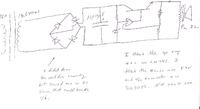
I used a circuit using an NPN power transister as the series pass element, an op amp, a zener diode and a voltage divider. I don't remember the component types and values. The circuit isn't here at home with me, but I'll try to find the schematic, although it won't indicate which resister values I changed it to to get the 12VDC on the output, instead of the 17V I originally designed it for. If I find it I will post it.

---------- Post added at 20:08 ---------- Previous post was at 20:00 ----------

I meant to mention that Although I could have used a three pin regulator , at the time I built it , I didn't know of a three pin regulator that could handle 3A, which is the load I was aiming for getting close to. I didn't know I was going to have to lower the output to 12V until after the whole thing was built. Otherwise I would have used a 3 pin chip,like a couple of the ones I found on the internet more recently. I think the whole problem is that I cheaped out on the transformer with one that was a lower output at 120VAC in than I originally wanted.

---------- Post added at 20:29 ---------- Previous post was at 20:08 ----------

This is all that I have right now:


I didn't mean to show the speaker right across the supply, but I had a brain hiccup. It comprises at least 95% of the load though.
 

With an NPN pass device your op-amp needs to drive the base higher than your expected output voltage,

**broken link removed**

For single supply operation the LM741 is only rated to a 22V rail which, if you are supplying it from your 13.6RMS/"18V rectified" supply would be OK.

However if you look at the available output voltage swing, and possibly current drive,


Then it suggests that the op-amp might only be able to raise its output, under load, to 5V below the supply input. So 18V-5V is 13V and then you have to account for the Vbe drop of 0.7V for your pass device and the maximum, nominal, output becomes 12.3V which sort of fits in with what you are seeing.

Regarding the maximum available current from your LM741 25mA typical is indicated. For a 2N3055 the current gain, hfe,

http://www.energies.alba-annuaire.fr/data/tr/2N3055.pdf


is specified as 20-70. You can also see from the above that the Vbe exceeds the 'rule of thumb' 0.7V at 4A causing more problems..

With 25mA typical available from the LM741 then using the maximum hfe of 70 your circuit would only be able to supply 1.75A, Ib.hfe, before it gave up.

There are 3 amp adjustable regulators available...

3A 3 terminal regulator - Google Search

http://www.fairchildsemi.com/ds/LM/LM350.pdf

However that one has an NPN Darlington configured output,


and as a result suffers from the same voltage drop out problems,


So you might consider a LDO, Low Drop Out Regulator..

3A 3 terminal LDO regulator - Google Search

Linear Technology - LT1085 - 7.5A, 5A, 3A Low Dropout Positive Adjustable Regulators

http://cds.linear.com/docs/Datasheet/108345fg.pdf

Grrrrrrrrr, which in itself is still using NPN pass devices and still needs 1V of headroom which will not be, or rather just is, available if you want 17V out from your 18V nominal input supply. Sorry, I'm just doing searches and hitting links, or lack of them. There will be more suitable devices out there. I'm not trying hard enough to find one but they do exist.

Perhaps you are ending up having to use such a large filter capacitance on your supply in order to avoid ripple affecting the regulator and probably need more input voltage. However, if I have read correctly, 18V in with 17V out is probably going to be unworkable so it looks like you will need a different transformer.

Genome.
 
Thank you. This is very detailed and helpful information Genome.
 

Thank you Genome, but I was still wondering how the manufacturers of the CD player keep the unit so small and still get more power out of it. I know they can use a switching supply and get more voltage, but the current still has to come from somewhere. A transformer bigger than the one I used wouldn't fit in that thing.
 

VA for the load , which is same whether linear or switched ,
is same.
but the high frequency is the key for the reduced transformer size in smps.
so , current is from the same trfr.
 

Status
Not open for further replies.

Part and Inventory Search

Welcome to EDABoard.com

Sponsor

Back
Top