Continue to Site

Welcome to EDAboard.com

Welcome to our site! EDAboard.com is an international Electronics Discussion Forum focused on EDA software, circuits, schematics, books, theory, papers, asic, pld, 8051, DSP, Network, RF, Analog Design, PCB, Service Manuals... and a whole lot more! To participate you need to register. Registration is free. Click here to register now.

Serial Communication problem with Atmega8

Status
Not open for further replies.

hardik.patel

Member level 5
Joined
Aug 15, 2012
Messages
94
Helped
1
Reputation
2
Reaction score
1
Trophy points
1,288
Activity points
2,008
Hi Friends,

I want to design wireless Device control using CC2500 Uart module.

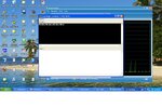
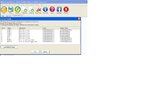
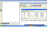
For transmitter part, i am transmitting a string which must be visible at hyperterminal.
But its not as expected. H/w is ok as i had tested it with other i/o operation.

Before this i had tried this with 16Mhz n 11.0592Mhz but though not succeed then i had followed to the datasheet, n replaced the crystal with 7.3728Mhz but still problem continued.
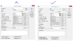
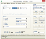
Even i had tried to reduce/increase the all Baud rate in Flash Magic with (16,11.0592n 7.3728Mhz) so kindly correct me that where i am wrong.

MCU-Atmega8
Compiler - AVR GCC Programmer's Notepad
Xatal= 7.3728Mhz
Module i used for wireless -http://www.sunrom.com/p/rf-serial-data-link-uart-2-4-ghz
(To work with module its a later part)

Code as well as screen shot of Hyperterminal is attached.


Regards,
Hardik

- - - Updated - - -

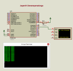
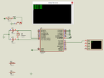
I had connect Tx-rx(MCU pin) with PC (via Max232's rx-tx pin)..so there is not problem with any h/w connection, I think.
 

Attachments

  • tx.rar
    84.6 KB · Views: 108
  • error12.jpg
    error12.jpg
    102.8 KB · Views: 152

Hi,

* a schematic could help
* and a scope picture of your signals where we can see timing and levels.
* and additional info to the scope picture like estimated baud rate and transmitted character.

Klaus
 

How is PIC interfaced to PC ? Using MAX232 and DB9 connector or using TTL2USB or RS232 to USB adapter and USB port of PC ?

If interfaced to COMx port of PC using RS232 then have you set the proper baudrate for your COMx port in Device Manager > COMx port properties ?
 

@milan,

1) I am using Atmega8 not PIC
2) Atmega8 interfaced to comport1 via Max232 n DB9 Connector
3) Also configured COMx Properties well as you can see in picture.
4) Also i had tested comport connection using loopback testing method that i can see whatever i typed in i/p on o/p at a flash magic's terminal window.
 

Attachments

  • comport.jpg
    comport.jpg
    102.5 KB · Views: 126
Last edited:

4) Also i had tested comport connection using loopback testing method that i can see whatever i typed in i/p on o/p at a flash magic's terminal window.

In Flash Magic have you set baudrate to 9600 bps and did the loopback test ? If yes, did you get the proper output (echo) ?
 

Code is correct. Maybe F_CPU has to be declared. I am not sure.

Try this code. I have tested this in Proteus and it works fine. I have used AVR Studio 4.18 and WinAVRGCC.


Code C - [expand]
1
2
3
4
5
6
7
8
9
10
11
12
13
14
15
16
17
18
19
20
21
22
23
24
25
26
27
28
29
30
31
32
33
34
35
36
37
38
39
40
41
42
43
#define F_CPU 7372800
 
#include<avr/io.h>
#include <util/delay.h>
 
void UART_Init(unsigned int baudrate) {
 
    unsigned int baudPrescale = 0;
 
    baudPrescale = (((F_CPU / (baudrate * 16UL))) - 1);
 
    UBRRL = baudPrescale;
    UBRRH = (baudPrescale >> 8); 
    UCSRC = (1<<URSEL) | (1<<UCSZ1) | (1<<UCSZ0);  
    UCSRB = ((1<<TXEN)|(1<<RXEN) | (1<<RXCIE));
}
 
void UART_Write(char data) {
    while(!(UCSRA & (1<<UDRE)));
    UDR = data;
}
 
void UART_Write_Text(char *data) {
    while(*data) {
        UART_Write(*data++);
    }   
}
 
int main(void) {
    
    DDRB = 0xFF;
    DDRC = 0xFF;
    DDRD = 0xFF;
 
    UART_Init(9600);
    _delay_ms(200);
    
    while(1) {
    
        UART_Write_Text("ATMega8 UART\r\n");
        _delay_ms(1000);
    }   
}


broken link removed
 

Attachments

  • UART.rar
    47.8 KB · Views: 92
  • uart.png
    uart.png
    27.5 KB · Views: 272
Last edited by a moderator:
I had compiled your given code with AVR-GCC notepad but proteous result not as per your picture shown.

Even i had fed your .hex to proteous file....still its not as per picture, garbage character shown.
I had attached my proteous n gcc folder here....simulate it.

- - - Updated - - -

is there need to set fuse bits for this task??....because i dont had idea about it. N even not set so far in past.
 

Attachments

  • milan_serial.rar
    69 KB · Views: 89

Your code is correct. The problem is with your Proteus settings. Don't use crystal in Proteus. It doesn't generate clock. It is a dummy model. Instead set clock frequency in Edit Properties dialog of MCU in Proteus. See images for settings. I don't have Proteus 7.x. I imported your Proteus file in Proteus 8.2 SP2 and after setting the clock frequency and WDT settings properly it worked. See image.

broken link removed
 

Attachments

  • uart.png
    uart.png
    33.4 KB · Views: 165
  • uart1 settings.png
    uart1 settings.png
    40.9 KB · Views: 153
  • milan_serial proteus settings fixed.rar
    163.8 KB · Views: 133
Last edited by a moderator:
Ok....after followed your suggestion i got same result in proteous.

Now for h/w what should i need to change?
(for fuse bits, external clock freq)

does anything required those??
 

I have used external clock frequency that is crystal of 7.3728 MHz. Use the exact crystal or use easily available 4, 8, 12, 16, 20 MHz Crystal and change F_CPU value in code and compile. I don't know whether you had enabled the WDT or not. I simply disabled WDT in Proteus. If you enable WDT then you have to make sure it is cleared properly in code. I don't have the IDE you are using. What fuse bits your fuse bits setting windows show ?
 
Even i using same 7.3728 crystal for h/w also.
N does there is necessary to enable/disable WDT ??

I am using Win-avr GCC compiler. N i dont know that how to set fuse bits using AVRGCC.
 

I am showing you an example of setting fuses. I have used mikroE's AVR Flash tool. You have to do similar fuse settings in your Compiler's IDE or Programming software.
 

Attachments

  • fuse bits.png
    fuse bits.png
    29 KB · Views: 111
Hi,

I have used external clock frequency that is crystal of 7.3728 MHz.

AFAIK there are two different settings for:
* crystal and
* external clock.

If you use an external crystal oscillator (with VCC and GND connection) then choose "external clock"
If you use a passive crystal with two capacitors and a resistor then use "crystal"

Klaus
 

@Klauss..
here i upload two pictures, from that kindly tell me for this task which fuse bits i need to set?

in s/w does i need to set fuse bits or while i programmed the chip??

n does this error that i cant getting same result as proteous on h/w is due to that??

- - - Updated - - -

@to all

If i not set the fuse bits....is this the cause of not getting proper o/p on hyperterminal in my case??
 

Attachments

  • fuse1.jpg
    fuse1.jpg
    54 KB · Views: 117
  • fuse2.jpg
    fuse2.jpg
    93.7 KB · Views: 122
Last edited:

Hi,

read datasheet chapter 8.2

use "External Crystal/Ceramic Resonator"

If you don´t have a battery poweredapplicatio then I recommend to program (=0) CKOPT.

Klaus
 

In my appliaction the MCU will be provided a Power supplied from the DC Source.
N i using External Crystal 7.3728Mhz
 

Hi,

If i not set the fuse bits....is this the cause of not getting proper o/p on hyperterminal in my case??
for sure it makes a difference wether the clock is internal 1MHz or crystal 7.3728MHz...
Baudrate depends on this clock frequency.

Klaus
 

i had also read that topic in Datasheet of Atmega8, but not clear understand that how to set fuse bits??
wheather in s/w or while chip programming?
 

Hi,

Chaper 23.6:
Note that the fuses cannot be changed by the MCU itself.
This means: not per s/w, but programming.

Klaus
 

Status
Not open for further replies.

Similar threads

Part and Inventory Search

Welcome to EDABoard.com

Sponsor

Back
Top