Continue to Site

Welcome to EDAboard.com

Welcome to our site! EDAboard.com is an international Electronics Discussion Forum focused on EDA software, circuits, schematics, books, theory, papers, asic, pld, 8051, DSP, Network, RF, Analog Design, PCB, Service Manuals... and a whole lot more! To participate you need to register. Registration is free. Click here to register now.

Self Bias Transistor relation

Status
Not open for further replies.

mohammadyou

Member level 4
Member level 4
Joined
Oct 2, 2007
Messages
76
Helped
2
Reputation
4
Reaction score
2
Trophy points
1,288
Visit site
Activity points
1,785
Hi
I haven't worked with transistors for period of times. based on the voltage divider relation for two resistor it was suppose that we have VB=VCC ×(R2÷(R1+R2)) so VB= 14V
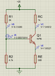
Transistor.png
By this voltage we have negative VCE on paper.
because of the static resistor (rs) and being IB>I2 (current in the R2 resister) our assumption (Voltage Divider) was incorrect but when I calculate the value of rs and put in parallel with R2 resistor, I still can't find the value Of VB and IB.
Would you please give me any useful references or information that how can I find the values by hand.
 

Thanks barry for your reply
You're right. I was tried to solve the problem by approximation (if I2>>IB i think it could be correct) but even so with IB>0 and take the rs into account i still cant find the answer . I've should made a mistake of finding Ib would you please give me a good reference (book ...).

Do you really need a book for the finding of proper resistor values?
Start with a suitable collector current Ic (given supply voltage) and find the corresponding base current Ib=Ic/beta.

Select a current through the base divider (I1=k*Ib) with k=6...10
and calculate the resistors R1 and R2 using Ohms law and the base voltage Vb=0.7+Ic*Re.

That is the classical approach to design a common emitter stage.
 

Given that Vbb ~ 14V, therefore Ve = Vb -.8 =~ 13.2 V, So Ie ~ 13.2/500 = 26.4 mA. BUT if Ic = 26.4 mA, then the volt drop across the 1K = 26.4 V. . . Some thing not quite right here... In real life the transistor is switched hard on so the Vcc is across the Rc and Re and allow .2V for the transistor. so 19.8 V across 1.5 K = 19.8/1.5 mA = 13.2 mA, So Ve = 19.8 X 500/1500 = 6.6 V and Vc = 6.8V. This would be true if the base current was a reasonable value, say Ic/100. The problem is its HUGE, your resistors give about 4.7 X 20 /6.7 as the voltage ~ 14 v with a source impedance of the 2 K and 4K7 in parallel ~ 1.6, So voltage driving Ib = 14 - 6.6 = 7.4 V, so I b ~ 7.4/1.6 ~ 4.5 mA. So its a really weird circuit.
Good way to get started, select a Ic (5 mA?), select Vcc, allow for 10% of Vcc across emitter resistor, so Vb = 10% Vcc +.8v, so work out your resistor chain to give this value if the current through the chain is 10% Ic. Ignore Ib, its < 1 % Ic. Select Rc so Vc lies half way between Vcc, and Ve +.5V. it might not be pretty but it will work! :)
Frank
 
Status
Not open for further replies.

Similar threads

Part and Inventory Search

Welcome to EDABoard.com

Sponsor

Back
Top