Continue to Site

Welcome to EDAboard.com

Welcome to our site! EDAboard.com is an international Electronics Discussion Forum focused on EDA software, circuits, schematics, books, theory, papers, asic, pld, 8051, DSP, Network, RF, Analog Design, PCB, Service Manuals... and a whole lot more! To participate you need to register. Registration is free. Click here to register now.

SCR Gate Driver arduino?

Status
Not open for further replies.

stringerbell

Junior Member level 1
Joined
Mar 24, 2016
Messages
15
Helped
0
Reputation
0
Reaction score
0
Trophy points
1
Activity points
139
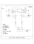
I was wondering if any of you could help me understand a bit more how the IRKT 91 12 "back to back SCR" can be driven in a cost effective way. I have found this circuit on a closed tread on here:
pedal.jpg

I'm not understanding all of what im reading, i just watched some 1 hour explanation to zero crossing in ac systems, and its importance in scr switching, if i understand correctly the capacitors give the delay the gates need in the above circuit, to prevent a a short, i see gate drivers online like this one

https://www.nuwaveproducts.com/Data...ower-Control-Gate-Driver-Board-Zero-Cross.pdf

If im understanding correctly i could simply input 0-5v and it will take care of the rest. This looks like the way i would like to add an arduino down the road will this work? i have also seen complex arduino projects with complex for me zero crossing circuits and pulse train drivers with coding way beyond my ability.
 
Last edited by a moderator:

Hi,

First some warnings.
You are posting in the hobby section of the forum...
Working with mains voltage is dangerous. Mind that all the circuitry is dangerous to touch. Even the wires to the pot and the pot itself. It needs a special pot that is rated for thathigh AC voltage. Mind that if there is a test voltage of about 250V, then it is far from being safe. Consider to use parts with about 3000Vof test voltage fore safety isolation.

Especially the connection to an arduino with its "undangerous" style needs a lot of safety air gaps and creepage distance between mains and low voltage.

The circuit is technically critical. Because the trigger for the positive halfwave is independent from the negative halfwave you may expect difference in phase angle. This leads to DC voltage in the transformer, causing high DC current and explosion of an Scr.
Inductive loads are difficult to drive.

Do want to drive an inductive load?
I recommend to use a properly isolated zero cross detection circuit. And use two independent properly isolated Scr drive curcuits.
With an arduino i recommend to use a PWM output to drive the trigger circuits.

Put all the mains voltage parts in a plastic box. Use an RCD.

Klaus
 
thank you, and i was aware, i seen with aurdino people use LED opto isolaters making it 100% safe, so i think with carfull planning ill be safe, thanl you very kindly for the concern and time you took to relize that theres this hazard and i was wondering the gate driver in link so looks isolated by design is it?
 

Hi,

i was wondering the gate driver in link so looks isolated by design is it?
It is isolated, for sure. But if the distances and devices follow the safety regulations of you country... I don´t know.

****
The circuit is for back to back SCR with zero cross switching.

* with zero cross switching you can´t run a phase control. Just on and off or full/half wave packet control.
* for ON / OFF you don´t need a zero cross detection circuit.
* if back to back SCR, why not use a simple triac?

Klaus
 
if its of any concern its for a Old ESAB arc welder (non SCR) if i has the skills required, i would figure out how to do all these angle controls and stuff, but at end of the day im noob so current control is the best ill likely achieve, if i can get a full wave i wont lose any output (if i was using half wave id lose 50% (if i understand that right), when i see the triac i see 3 pins, one of them is the gate that opens the flow between the two other pins, i dont understand how to use that (are you suggesting the collector and the other pin can be put in between the K1 and G1 and the gate then triggers and closed the g1 to k1 and i would prolly use a resistor in there to?
 

Hi,

a triac is simialr to two SCRs. The gate control is different.

With two SCRs you need two gate controls.
With a triac you only need one gate control. A signal at the gate triggers the triac and it is low impedance (in either polarity) until current crosses zero line.

With a transformer or any other inductance as load you urgently need to avoid unsymmetry in both polarities (halfwaves). Otherwise the fuse will blow...in best case..


Klaus
 

Ok i think i got that, but can i find a 220v triac that can do 20 amps AC? sounds like i see videos on youtube of people with 600w triacs controlling motors in a way i understand, the gate firing theory you explained well so i got that. Triac it is if i can find one
 

Hi,

a quick view into farnell´s selection tool for triac >400V, >20A RMS gives 66 results...


Klaus
 

Last edited:

Hi,

if its 20amps at 400v isnt that only good to ~10 amps on 230v?
No. 20A rating is 20A rating...

Your linked device should work.
Trigger it with a gate current of at least 120mA. With this triac yor gate voltage is independent of line voltage --> You may trigger positive and negative halfwave with the same gate polarity.

Klaus
 
so for my welder which draws 20 amps 220AC MAX your saying this is all i need to do is put that little chip in between L1 going to transformer and other pin to line, (opto isolate gate for safety), but with this system https://i.stack.imgur.com/QxcbW.jpg so with a (TRIAC) zero crossing happens automatically or it's just irreverent? and will i still get full current to the transformer which is inductive load or does that little chip cut the current ability in half?

- - - Updated - - -

imm watching all this guys videos there really good, do you think thats a curcuit well suited for what i want, from my understanding its perfect, sorry for the double post it wouldnt let me edit https://www.bristolwatch.com/arduino/arduino1.htm
 
Last edited:

sorry for the double post it wouldnt let me edit

After you post a message, the system gives you a few minutes to go back and re-edit it. Or, you can post a follow-up, and it gets appended to your preceding post (which is what happened as you can see).
 

my electronics store in town only have 400v 25amp triac, should be ok right?
partstriac.jpg
 
Last edited by a moderator:

Hi,

so with a (TRIAC) zero crossing happens automatically or it's just irreverent?
The zero cross switch ON is not determined by the triac nor the SCR. It is determined by the driving circuit.

Klaus
 

Yeah i have been at this all day, the circuit i'm now following is using the ardrino and the zero crossing (i accidentally bought 250v max optocoupers though i see its intended for 120v (the MOC3010) I want the MOC3020 i for 220..... mistakes always to be made. So im just playing around tonight trying to dim a light bulb i also didn't get the snubber cap or resistor so ill stick to a incandescent bulb on 120 for now, but, how much harder would it be to control the back to back SCR vs the TRIAC being that im already going to implement zero crossing, and i see alot of these MOC's have something about zero crossing (for instance MOC3060) but im doing this externally with the audrino so whats the purpose of the "zero crossing" in the MOCS
 
Last edited:

Hi,

If you don't want phase control (just control complete full or half waves):
Then you don't need a zero cross detection circuit.

Your driver circuit has zero cross trigger. This means it can't be used for phase control. It is not possibke to trigger the SCR/triac at a desired phase angle, it always starts at zero cross. This is good to avoid electromagnetic emissions.

If you want phase control:
Then you need a zero cross detector for the microcontroller to know when to start the delaytime for the desired phase angle. You then need driver circuit for immediate triggering the scr/triac (in opposite to zerocross triggering)

Klaus
 
ok so if im understanding now, something like a moc3010 (non zero firing internally) can be triggered at any point of the wave like in


[image at www . circuitstoday . com/wp-content/uploads/2009/09/SCR-Pulse-Control-Circuit.jpg]

Now with a micro-controller my assumption is; when i add zero crossing circuit into it the controller it will know where i am in the ac wave regardless of how i trigger it, now if i put on MOC3060 in it (says zero crossing) that actually wont let the MOC close unless im on zero (so if im understanding its a another way to make sure you fire just at zero) (not what i want) now from looking at the code it looks like the micro-controller knows its zero when the 5 v pulse gets input into the controller and then in controller, then you tell it how many microseconds to delay, then it fires, changing this delay would alter when the triacs firing position (if it was to late im not geting all the power i could)
 
Last edited by a moderator:

Hey guys got that Triac curcuit working great with a snuber for my fume extractor fan on my welding table, i have it hooked up to trigger with a reed switch so it speeds up when the welder is going. but now i want to make use of my IRKT91 back to back SCR module, i want a turn key solution this time with little ardrino coding, so i was wondering if this board is best suited for a SCR back to back for a inductive transformer load, it seems to have a lot of extra features. https://www.nuwaveproducts.com/Datasheets/NWIPCM-1P-SCR-Power-Control-Phase-Angle-Driver-Board.pdf
 

Hi,

it seems to have a lot of extra features.
I can't see the extra features.
What extra features do you see?

Klaus
 

Status
Not open for further replies.

Part and Inventory Search

Welcome to EDABoard.com

Sponsor

Back
Top