Continue to Site

Welcome to EDAboard.com

Welcome to our site! EDAboard.com is an international Electronics Discussion Forum focused on EDA software, circuits, schematics, books, theory, papers, asic, pld, 8051, DSP, Network, RF, Analog Design, PCB, Service Manuals... and a whole lot more! To participate you need to register. Registration is free. Click here to register now.

schematic using LM317 and opto-isolator

Status
Not open for further replies.

vaibhavpawar

Junior Member level 1
Joined
Nov 9, 2014
Messages
19
Helped
0
Reputation
0
Reaction score
0
Trophy points
1
Visit site
Activity points
178
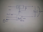
I have made following circuit, in which I have connected isolator and LM 317.
ps.png

Opto-isolator is connected between Controller I/O pin and LM317 output. Will this circuit work, especially I am confused about the grounding scheme..when transistor conducts, will this circuit pull down one end of load to Gnd ( since transistor conducts when I/O pin is gnd ).

Is this feasible design to implement?

Thanks in advance.
 

Load is 3V laser source.

Details of Laser: 650nm 6mm 3V 5mW Laser Dot Diode
 

It should work with a low current like that but it would be better to use the opto to drive a transistor. Reason: the internal transistor in most opto-isolators is only rated to carry a few mA, this is ample to bias an external transistor but may not be enough to handle the laser current by itself.

Also make sure you use a series resistor in the LED side of the isolator to limit it's current to a safe level.

Brian.
 
Thanks for reply, betwixt. But can you show me in schematic..how to drive external BJT with opto transistor and what value can we connect to anode of LED before connection with 5V.
 

I only have a mobile device to connect to the internet at the moment so I can't easily draw schematics but this is how you do it:

Two methods, both similar:

Connect the emitter of the new NPN transistor to ground.
Connect the collector of the new transistor to the bottom of the load.
(the new transistor is wired like the one already in the opto-coupler)

Method 1.
Connect the collector of the opto transistor to the output of the LM317.
Connect the emitter of the opto transistor to the base of the new transistor through a 1K resistor.
Connect the base of the new transistor to ground through a new 100K resistor.


Method 2:
Leave the emitter of the opto transistor comnnected to ground.
Connect the collector of the opto transistor to the base of the new transistor.
Connect a new 1K resistor between the base/opto junction and the output of the LM317.

Method 2 uses one less component but it inverts the way the logic drive works. In other words, the laser is on when the logic input is high instead of low. You may need to change the software to reverse the activation signal.

The resistor in series with the LED side of the optocoupler is calculated by:
(VCC - Forward voltage of the LED)/LED current. Use the data sheet to find the optimum current for your chosen device. For example if VCC is 5V and Vf is 1.6V and the LED was to pass 10mA, the resistor would be (5 - 1.6)/0.01 = 340 Ohms so the nearest standard value would be 330 Ohms.

Brian.
 

In method 1, emitter of opto transistor connected to base and you are saying base connected to gnd through 100 K. Brian, I am little bit confused....Please draw schematic for my understanding... really it will be great help.
Thanks
 

Sorry for the late reply.

The collector of the opto transistor goes to the output of the regulator.
The emitter of the opto transistor goes through a 1K resistor to the base of the new transistor.
As well as the 1K resistor, the base of the new transistor has a second new resistor of 100K to ground.

The 1K resistor is to limit the base current in the new transistor which otherwise might be high enough to damage it. The 100K resistor is to ensure the base of the new transistor goes to zero volts when the opto transistor turns off. Without the 100K resistor, if the opto transistor is not conducting the base of the new transistor would be left 'floating'.

Brian.
 

Status
Not open for further replies.

Similar threads

Part and Inventory Search

Welcome to EDABoard.com

Sponsor

Back
Top