byronboy
Newbie level 4

- Joined
- Jan 4, 2013
- Messages
- 5
- Helped
- 0
- Reputation
- 0
- Reaction score
- 0
- Trophy points
- 1,281
- Activity points
- 1,323
Hi, guys.
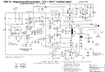
I am repairing a fairly new mercury 2500w 12v power inverter for a friend of mine which initially when connected to a 12v car battery and switched on gave no 230v ac output.The green power led was lit and no fuses blown.I checked all the mosfets and found no fault.It is quite a sophisticated design
using 16 irf1404 fets and 2 banks of 4 transformers in some parallel arrangement eventually driving into 8 18n50 fets.It also has 2 ka7500 and 1 LM325n ics.I discovered 4 in4148 diodes s/c hidden under one the transformers.I replaced them now the inverter works with a 60w bulb as a load.I measured the AC output.With no load connected the output was correct at 230v,but when the bulb is connected the output seems to rise to about 260v.I don,t wish to connect a heavier load at this stage.It is of far eastern design like most are so any current schematic would be helpful.
Many thanks, Byronboy, from Cornwall, UK.