Continue to Site

Welcome to EDAboard.com

Welcome to our site! EDAboard.com is an international Electronics Discussion Forum focused on EDA software, circuits, schematics, books, theory, papers, asic, pld, 8051, DSP, Network, RF, Analog Design, PCB, Service Manuals... and a whole lot more! To participate you need to register. Registration is free. Click here to register now.

schematic for adjustable current limiting circuit 0-3A 0-30V input and output voltage

Status
Not open for further replies.

xReM1x

Member level 5
Joined
Mar 25, 2014
Messages
83
Helped
0
Reputation
0
Reaction score
0
Trophy points
6
Activity points
586
hi.
I'm desiging switch mode power supply using the "LM2576-ADJ",
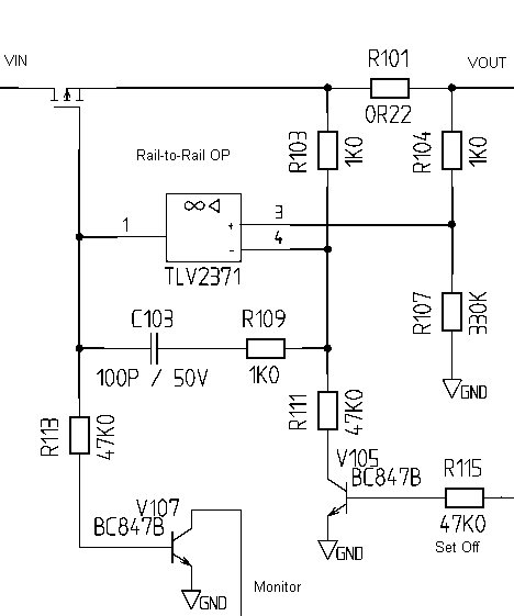
I need to add a pot to limit the output current. I tried googling it and all I found is using the lm317 and more crap. I need it to be as cheap as possible. so, basically the current limiting schematic should be 3.3V to 30V output, if I put 15V in, the output should be 15V, and that I can adjust the output current, and not the output voltage like most of the schematics I saw. Vin = Vout, Iout = set by potentiometer. Hope I explaind what I need.
thanks. :)
 

hi.
I'm desiging switch mode power supply using the "LM2576-ADJ"

The most easiest and cheapest way I can suggest you to play with On/OFF pin of LM2576. Use any open collector voltage comparator (eg. LM339) and limit your current by swithing On/Off of your regulator.
 

For a fixed load, you can't set the voltage and the current at the same time. For one particular voltage and one particular current, there should be only one particular load resistance (ohm law).

Regarding LM2576, its feedback comparator has an internal 1.2V reference. If you want a simple way to limit the output current you should put a shunt resistor (ground referenced) in series with the load and adjust it to have a voltage drop of about 1.2V across its terminals for the desired limiting current.

An adjusting shunt resistor it's pretty uncommon though. You better use a fixed (and much smaller) one then use an opamp with a manual adjusting gain to amplify the voltage drop acroos the shunt, to reach that threshold voltage (1.2V).

Or you can use that LM317 as a constant current source (a variable resistor between its OUT and ADJ terminals).

- - - Updated - - -

Keep in mind that once you force it to a constant output current, the outpul voltage isn't controlled anymore (unless you're supplying that current to a LED string, a rechargeable battery or something like this - with a variable internal resistance).
 

You should use OPAMPs. One for convert the current from shunt resistor, one for summarasing voltage from output with output of first opamp. And calculate the feedback resistors. Use a variable pots for regulate the feedback.
 

The most easiest and cheapest way I can suggest you to play with On/OFF pin of LM2576. Use any open collector voltage comparator (eg. LM339) and limit your current by swithing On/Off of your regulator.
As much as I know the ON/OFF pin is only the switch on and off the lm2576. how can I make it also control the output current? it doesnt make senes to me.
 

LM2676 has a so called "cycle-by-cycle current limiting" function. By driving its ON/OFF pin with a PWM signal, you could force the output to OFF state till the end of the current (internal) clock period, thus reducing the internal PWM duty cycle. But, once again, you still need some external components for that.
 

LM2676 has a so called "cycle-by-cycle current limiting" function. By driving its ON/OFF pin with a PWM signal, you could force the output to OFF state till the end of the current (internal) clock period, thus reducing the internal PWM duty cycle. But, once again, you still need some external components for that.
mine is 2576 not 2676.
 

As much as I know the ON/OFF pin is only the switch on and off the lm2576. how can I make it also control the output current? it doesnt make senes to me.

Current is depend upon load. Therefore, you can set the Maximum current limit through comparator. As soon your load current crosses the limit ur regulator switched off.
 

Current is depend upon load. Therefore, you can set the Maximum current limit through comparator. As soon your load current crosses the limit ur regulator switched off.

This way, you can at best implement "hick-up" current limiting but no continuous limiting.

if I put 15V in, the output should be 15V, and that I can adjust the output current, and not the output voltage like most of the schematics I saw. Vin = Vout, Iout = set by potentiometer.

You should observe the minimal voltage drop and maximal buck converter duty cycle of different switch mode ICs. LM2576 has e.g. 1.4 V typical saturation voltage and 98 % duty cycle limitation, so you won't get more than 13.3 V output.
 

This way, you can at best implement "hick-up" current limiting but no continuous limiting.


You should observe the minimal voltage drop and maximal buck converter duty cycle of different switch mode ICs. LM2576 has e.g. 1.4 V typical saturation voltage and 98 % duty cycle limitation, so you won't get more than 13.3 V output.
15V was an example. the voltage is going to change and I'm aware of the voltage drop and the other things.
but, I still havent found a good solution. the thing with the pwm is not exacly what I need.
I wonder if there is some type of "current regulator" that works like a voltage regulator, but that can control the current and not the voltage.
 

To adjust current to a fixed load you have to increase the voltage to force more current to flow. Or decrease the voltage to limit the current.

Current = Voltage / Resistance

The resistance is your load.

And the resistance is fixed, so you can only adjust the voltage to change the current.
 

I wonder if there is some type of "current regulator" that works like a voltage regulator, but that can control the current and not the voltage.
Do you mean a linear current regulator? You can make it using a MOSFET, an OP, a shunt and some additional components.
 

To adjust current to a fixed load you have to increase the voltage to force more current to flow. Or decrease the voltage to limit the current.

Current = Voltage / Resistance

The resistance is your load.

And the resistance is fixed, so you can only adjust the voltage to change the current.
Adjust the limited current, and not fixed load, its for a power supply so anything can be connected and I need to LIMIT the current that is following. lets say I connect an LED to the power supply, it can be anything but for an example LED, and I want to limit the current to 20mA, or 30mA, or 3A. so I need adjustable current limiting circuit.
 

The attachment should give the basic idea how to make a current limiter. You can add adjustable limit by a variable voltage divider or reference voltage.


The attachment should give the basic idea how to make a current limiter. You can add adjustable limit by a variable voltage divider or reference voltage.

What is the "set off" pin and what is the "monitor" pin?
and after I figure out were the voltage divider goes and how to calc the resistors, if I build this schematic it is supposd to give me adjustble current limit up to 3A?
 

What is the "set off" pin and what is the "monitor" pin?
I thought some things to be self-explanatory...

"set off" - a means to switch the output off
"monitor" - a line that indicates if the circuit is operating in current limit or not

it is supposed to give me adjustble current limit up to 3A?
Yes, according to suitable circuit parameters, e.g. MOSFET and shunt rating. Generally considering ohms law.

Designing the circuit for 3A range makes it difficult to set e.g. 20 mA exactly. Not a property of the circuit in particular but of the involved component parameters, e.g. OP offset voltage.

Another general remark. Operating a linear current limiter at higher currents involves large power dissipation for the output transistor (P = I*V). The monitor/set off lines may cooperate with a circuit that shuts the circuit down after a certain time of continuous limiting.
 

I thought some things to be self-explanatory...

"set off" - a means to switch the output off
"monitor" - a line that indicates if the circuit is operating in current limit or not


Yes, according to suitable circuit parameters, e.g. MOSFET and shunt rating. Generally considering ohms law.

Designing the circuit for 3A range makes it difficult to set e.g. 20 mA exactly. Not a property of the circuit in particular but of the involved component parameters, e.g. OP offset voltage.

Another general remark. Operating a linear current limiter at higher currents involves large power dissipation for the output transistor (P = I*V). The monitor/set off lines may cooperate with a circuit that shuts the circuit down after a certain time of continuous limiting.
thanks for your help. I would wait to see if someone have other options that works better or just easier.
 

As far as linear current regulators go, the above circuit is basically it. It doesn't get much better or simpler (understanding that you could remove the monitor and on/off controls). All linear solutions will give off the same amount of heat.

One alternative would be to work an external current control loop into the feedback network of the LM2576-ADJ. This would take a similar form as the above circuit (opamp sensing a resistor) but the opamp would drive back into LM2576-ADJ adjust pin. This would be a lower bandwidth solution and you'd have to be careful about the stability implications.
 

Status
Not open for further replies.

Similar threads

Part and Inventory Search

Welcome to EDABoard.com

Sponsor

Back
Top