Continue to Site

Welcome to EDAboard.com

Welcome to our site! EDAboard.com is an international Electronics Discussion Forum focused on EDA software, circuits, schematics, books, theory, papers, asic, pld, 8051, DSP, Network, RF, Analog Design, PCB, Service Manuals... and a whole lot more! To participate you need to register. Registration is free. Click here to register now.

Saturable reactor as a diode

Status
Not open for further replies.

neazoi

Advanced Member level 6
Joined
Jan 5, 2008
Messages
4,123
Helped
13
Reputation
26
Reaction score
15
Trophy points
1,318
Location
Greece
Activity points
36,955
From this website (around the bottom) https://www.ibiblio.org/kuphaldt/electricCircuits/AC/AC_9.html

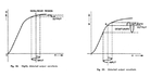
"saturable reactors tend to regulate AC power only in one direction: in one half of the AC cycle, the mmf's from both windings add; in the other half, they subtract. Thus, the core will have more flux in it during one half of the AC cycle than the other, and will saturate first in that cycle half, passing load current more easily in one direction than the other"

I am trying to benefit from this behaviour to built an "imperfect" diode using a saturable reactor, with no success yet.

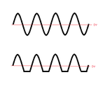
Here is a diagram of what I am trying to experiment with. I have tried DC in one winding and 7MHz AC in the other. A few turns in both, at about 100mA to 1.5A max. I have used one of these tiny (1mm) computer memory square loop cores

Any ideas would be helpful.
 

Attachments

  • Untitled.png
    Untitled.png
    39.4 KB · Views: 74

This looks like the magnetic amplifier concept. If your transformer had a sharper knee in its saturation curve, then you might be able to adjust the action to make an imperfect diode. It would have no voltage threshold (whereas diodes do have a voltage threshold).

Here is a webpage which talks about a magnetic amplifier being able to obtain an intermediate output voltage which would not normally be available using diodes.

**broken link removed**

"Magnetic Amplifiers in a Nutshell...Now, why do you see these mag amps in power supplies? Because they need 3.3V, but are only wound for 5 and 12V. What they do is this: if you half-wave rectify the 5V winding and filter it, you'll get half, or 2.5V, which is too little. If you full wave rectify, of course, you get 5V, which is too much. So this mag amp inductor goes in series with one leg, so when it's "out of circuit" (biased to full inductance), the output is essentially half-wave rectified, so it will make 2.5V."
 
  • Like
Reactions: neazoi

    neazoi

    Points: 2
    Helpful Answer Positive Rating
I'm under the impression that neazoi is still behind the idea of making a rectifier with only nonlinear magnetic components (without diodes). But the quoted thread showed that this isn't possible.
 
  • Like
Reactions: neazoi

    neazoi

    Points: 2
    Helpful Answer Positive Rating
This is the only mention of a magnetic rectifier in the whole pdf.
 

Attachments

  • magnetic diode.JPG
    magnetic diode.JPG
    81.9 KB · Views: 77

I'm under the impression that neazoi is still behind the idea of making a rectifier with only nonlinear magnetic components (without diodes). But the quoted thread showed that this isn't possible.

Well not a diode for sure, but if the core is DC biased so as the input signal follows onto the knee of the BH curve then the "effect" will be the same as a rectifier diode (looking at the diagram at post #1). In other words, one end of the outpout sinewave will be clipped and the other will pass through.

The amount of clipping (how good is the "rectification") I think depends on how steep is the BH curve (square loop toroids best?) and the AC voltage of the input signal.

Am I wrong in my thoughts?

PS. I have not managed to notice any of these effects in my experiments yet.
 

The saturable reactor will surely achieve waveform manipulations according to it's nonlinear characteristsic. The point of the previous thread which I'm keeping on about is that it will never convert an AC into a DC current without the help of a real rectifier diode.
 
  • Like
Reactions: neazoi

    neazoi

    Points: 2
    Helpful Answer Positive Rating
The saturable reactor will surely achieve waveform manipulations according to it's nonlinear characteristsic. The point of the previous thread which I'm keeping on about is that it will never convert an AC into a DC current without the help of a real rectifier diode.

In other words, this clipping it too small?
 

In other words, this clipping it too small?
The restriction is qualitative rather than quantitative. There can't be a DC voltage across an inductor/a transformer winding.
 

The restriction is qualitative rather than quantitative. There can't be a DC voltage across an inductor/a transformer winding.

I tend to think the distortion from the semi-saturated core like in the diagram (correct me if I am wrong).
The first image is the input sinewave. The second is the bottom-clipped sinewave from the semi-saturated core.
Whereas this is distorted AC, some useful DC could be taken out of it, if a non-electrolytic capacitor is shunted at the output. But I may be wrong though.
The way I think of it is, the capacitor will be charged at positive portions and discharged at negative. Since the positive portions are larger, the capacitor will be positively charged in average.
 

Attachments

  • Untitled.png
    Untitled.png
    6.9 KB · Views: 70

In my view you are reproducing erroneous believe that has been already disproved in the previous thread. I know well about it because I also considered that a DC current could be generated under circumstances. But I recognized that the idea is wrong.
 

Status
Not open for further replies.

Similar threads

Part and Inventory Search

Welcome to EDABoard.com

Sponsor

Back
Top