vladm
Newbie level 3

Hello all;
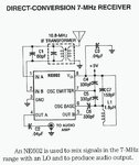
I am building a direct-conversion receiver for 3-4 MHz, which uses the SA602A chip for frequency conversion down to audio.
The SA602A is a double-balanced mixer IC with inbuilt oscillator circuitry.

I followed advice from the datasheet:http://www.alldatasheet.com/datasheet-pdf/pdf/107777/PHILIPS/SA602A.html
and this page: **broken link removed**
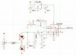
and designed a voltage-tuned oscillator (see attachments).
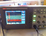
To test the circuit, I connected pin 1 to ground via a 10k resistor and pin 2 to ground via a capacitor and connected pin 4 to an oscilloscope. The result was a sinewave of about 50mV p-p, variable between 2.8 and 3.8 MHz according to the tuning voltage (see attachments). Connecting the probe to pins 7 and 6 also had the same result, with a smaller amplitude.
To preform the next test i set up the circuit as shown in the attached diagram and inputted a 1MHz signal from a signal generator (1MHz is the highest the sig gen could go, so with the oscillator set to 3MHz the output should show frequencies of 2 and 4 MHz).
Now here is the problem: disconnecting the 10k resistor from pin 1 stops the oscillator. The output pin just outputs the input signal, no heterodyning products seen whatsoever on the 'scope FFT display. Connecting the probe to pins 6&7 now shows no signal.
This is very odd, I thought that the oscillator is isolated from any other pins. I need it to mix input signals with the local oscillator, which it is not doing at the moment.
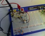
The circuit is currently built on breadboard (see attachments), I have been told that it's generally a bad idea to use breadboard for prototyping RF circuits. (It is fairly easy for me to make a pcb.) The mixer circuit in question on the image is center, bottom is an RF filter and far right is an AF amplifier.
I know of issues concerning the poor dynamic range of the SA602A, so I had set the voltage of the sig gen to be well within the dynamic range of the chip.
Any help or suggestions appreciated.
I am building a direct-conversion receiver for 3-4 MHz, which uses the SA602A chip for frequency conversion down to audio.
The SA602A is a double-balanced mixer IC with inbuilt oscillator circuitry.
I followed advice from the datasheet:http://www.alldatasheet.com/datasheet-pdf/pdf/107777/PHILIPS/SA602A.html
and this page: **broken link removed**
and designed a voltage-tuned oscillator (see attachments).
To test the circuit, I connected pin 1 to ground via a 10k resistor and pin 2 to ground via a capacitor and connected pin 4 to an oscilloscope. The result was a sinewave of about 50mV p-p, variable between 2.8 and 3.8 MHz according to the tuning voltage (see attachments). Connecting the probe to pins 7 and 6 also had the same result, with a smaller amplitude.
To preform the next test i set up the circuit as shown in the attached diagram and inputted a 1MHz signal from a signal generator (1MHz is the highest the sig gen could go, so with the oscillator set to 3MHz the output should show frequencies of 2 and 4 MHz).
Now here is the problem: disconnecting the 10k resistor from pin 1 stops the oscillator. The output pin just outputs the input signal, no heterodyning products seen whatsoever on the 'scope FFT display. Connecting the probe to pins 6&7 now shows no signal.
This is very odd, I thought that the oscillator is isolated from any other pins. I need it to mix input signals with the local oscillator, which it is not doing at the moment.
The circuit is currently built on breadboard (see attachments), I have been told that it's generally a bad idea to use breadboard for prototyping RF circuits. (It is fairly easy for me to make a pcb.) The mixer circuit in question on the image is center, bottom is an RF filter and far right is an AF amplifier.
I know of issues concerning the poor dynamic range of the SA602A, so I had set the voltage of the sig gen to be well within the dynamic range of the chip.
Any help or suggestions appreciated.