Continue to Site

Welcome to EDAboard.com

Welcome to our site! EDAboard.com is an international Electronics Discussion Forum focused on EDA software, circuits, schematics, books, theory, papers, asic, pld, 8051, DSP, Network, RF, Analog Design, PCB, Service Manuals... and a whole lot more! To participate you need to register. Registration is free. Click here to register now.

[SOLVED] Rising/Falling edge detector with positive output pulse

Status
Not open for further replies.

indemnity83

Newbie level 3
Joined
Aug 17, 2013
Messages
4
Helped
0
Reputation
0
Reaction score
0
Trophy points
1
Activity points
82
Rising/Falling edge detector with negative output pulse

I'm either doing something wrong, fried the chip, or just am in above my head.

I have an NTE74LS14 chip (Hex Schmitt Trigger Inverter http://www.nteinc.com/specs/7400to7499/pdf/nte74LS14.pdf) and was trying to following an article about edge detection **broken link removed** but I can't seem to get anything to work right.

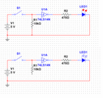
So I simplified; and still didn't get anything like I expected. I expected that with the switch open, the LED would be on and with the switch closed the LED would go out ... what am I doing wrong:

**broken link removed**
 

You need a current limit resistor in series with the LED. Put a 470Ω in series. Also put a 10k resistor on the input of the gate to ground. With the input left open the output will always be at zero.
 

Attachments

  • edge.gif
    edge.gif
    7.1 KB · Views: 262

The input to that 74LS14 assumes high unless drive it low or pull it low by sinking current from it. So it thinks the input is high regardless of the switch setting. Adding a resistor to ground at the gate input as suggested by E-design should fix it. As well as the current limiting resistor to the LED, you should have capacitors on both sides of the LM7805 to ground (the 'Com' pin) to ensure it's stability. These type of regulators tend to oscillate or produce wierd output voltages if the capacitors are left out. Try 10uF across the input and 100nF across the output.

Brian.
 

According to the data-sheet, when the output is high the gate can source a maximum current of Ioh=400 uA that is not enough to switch the LED on. When the output is low, instead, the gate can sink a current of Iol=8 mA (with Vout=0.35V typ). This means you can switch the LED on connecting it from Vcc (anode) to the output of the gate (cathode) using a series resistor. So if Vcc=5V and supposing a voltage drop on the led of 1.9V the resistor should be greater than:
R>(1.9-0.35)/8mA that is R>200 ohm. The already suggested value of 470 ohm is then OK.
Of course, doing so, you will have a reversed behaviour with respect to the original wanted by you: pressing the button the LED will be switched on.
As already said in the previous posts of E-design and betwixt, you have to add the input resistor to ground as well as the regulator's stabilizing capacitors.
 

Sweet, thanks guys ... so I got this working so far with the pull down resistor on pin 1 (I already had the decoupling capacitor and current limiting resistor, just didn't show it). So now, I can get understandable behavior from the following circuit:

**broken link removed**

So now to make this actually useful ... I'm ultimatly not driving an LED, but a clear/reset pin on a J-K Flip Flop. So I made the following changes highlighed in blue below and it works once, when I close the switch the first time. Any time after that it doesn't seem to work unless I pull off and replace the capacitor. I've tried a few different values of C2 it doesn't seem to make a difference, I'm not sure how to size some of these components.

**broken link removed**

I can share the entire schematic if it helps; but I'm worried that other issues with the circuit design might cloud the issue. **broken link removed** is a link to a logic.ly file I made which demonstrates the basic function I'm looking for; its essentially a multi-source control for a light system. One control is a momentary contact tactile switch that's user operated that toggles the light on or off, the second control is a 5v on/off signal from a controller. When the controller is turned from off to on, I want to the light to come on (Q on JK to be high) whether it was or wasn't already ... similarly when controller goes from on to off, turn the light off. I hope that makes sense. I'v been fiddiling with this for a while now and feel like I'm getting close, but I felt like I needed to reach out for some help on the edge detector / pulse generator portion.

Thanks.
 

C2 will be charged up after you first try. You then need to reset it by discharging it. Put a high-value resistor over it (or to ground from the switch end) to allow reset if the switch is open.

Below it shows what happens when you don't discharge C2. It works only once.
 

Attachments

  • edge1.gif
    edge1.gif
    27.6 KB · Views: 271
In you circuit the capacitor can't discharge. You can simply try to add a resistor from the input of the capacitor (SW side) to ground so that it can discharge when the switch is open. Roughly the time needed to discharge (then to retrigger), in seconds, will be given by (R1+R3)*C2 where R3 is the resistor to be added.
 

Sigh ... I have a lot to learn. That seems so obvious now that you say it. 1M ohm resistor seems to have worked like a charm too with a 100pF cap.
 

I'm so close now, but still lacking something basic ... just need to get the falling edge to work now; what am I doing wrong this time. I need both outputs to be negative pulses.

(also ... any good resource I could dig into to figure this out on my own in the future?)

**broken link removed**
 

The resistor after C3 should go to ground (you have two 'R1' by the way!)
If all you want is an inverted version of the original pulse, remove the new resistor and capacitor and simply link pin 2 and 5 of the IC. There's no point is duplicating a circuit when you can use the original. You could also try connecting C3 between pins 2 and 3 of the IC and taking the output from pin 4. In other words, creating a new pulse based on the old one.

Brian.
 

There are many books. CMOS and TTL cookbook are classics teaching many basic techniques.

https://www.amazon.com/TTL-Cookbook...8&qid=1376788216&sr=1-1&keywords=ttl+cookbook

Thanks ... added the book to my wishlist. Your design seems to work, but for some reason the falling edge isn't consistent in my breadboard hookup, might be switch bounce so I'll throw in a de-bounce circuit and see if that helps. Oddly enough the rising edge works flawlessly, but the falling edge seems to only rarely work. Or maybe its the resistor value pulling the input to U2 down (in your diagram) and C2 not being able to pick it up far enough? I'm not sure ... I see what you did, and that it worked in your simulator, but something about the rest of the circuit seems to be causing it to fail on my breadboard ... I'll continue to fiddle.

The resistor after C3 should go to ground (you have two 'R1' by the way!)
If all you want is an inverted version of the original pulse, remove the new resistor and capacitor and simply link pin 2 and 5 of the IC. There's no point is duplicating a circuit when you can use the original. You could also try connecting C3 between pins 2 and 3 of the IC and taking the output from pin 4. In other words, creating a new pulse based on the old one.

Brian, I'm not just looking for an inverted version of the original pulse; I need separate negative pulses on both the leading and falling edge of stateful control signal (in the case of my breadboard test, a toggle switch)
 

On a breadboard, you have stray capacitances between all connections that can affect your circuit. Try to increase the 2k and cap values ten times and see if you get better performance.
 

I fiddled with different r values; another odd problem crops up though in that just about anything higher than 2K on R3 (your schematic) seems to not act as a pull down, and the output is off/low. I will probably have to go run to the store and pickup a new multimeter to check some things out, mine seems to have gone AWOL during a recent move.
 

Keep the 2k and increase the C value to say (560pF to 1nF). I personally prefer to work with CMOS devices where possible, unless I can't avoid it due to speed limitations.

In my book, the minimum value for C is suggested at 330pF.
 
Last edited:

Still having trouble. I've tried the 100pF, 330pF, 560pF, 1nF (even a 56pF for grins) ... there must be something I'm doing wrong. My breadboard is a mess because of all this experimenting, I'll tear down and rebuild it to see if I inadvertently have something out of place. I also picked up a book "Practical Electronics for Inventors" that seems to cover the whole spectrum of circuit design.

For now, here is the full circuit that *should* be working by all accounts (I probably still need to optimize R and C values throughout)

**broken link removed**

- - - Updated - - -

After looking at it ... I'm wondering if R6 is probably causing me some grief. I didn't realize I had my debounce setup like this until I drew it up in the schematic.
 
Last edited:

R6 shouldn't be a problem although I would drop it's value to say 4.7K. Better to short out R5 and place a low value resistor in series with the switch, say 100 Ohms. If the other gates in the 74LS14 are not being used, wire two in series between C4 and the 74LS109. The 74LS14 is a Schmitt input device so it will to some extent clean up the rise and fall of voltage across C4. You need two to correct the inversion of the signal.

Brian.
 

VICTORY!

It ended up being way simpler than I was making it. I think I was having trouble with the switch (SW2 in the attachment); I was using a mechanical switch and the bounce may have been causing me grief. I switched to using an Arduino as a digital switch (which is more representative of my final circuit) and things started falling into place.

Switch Debounce.PNG

- - - Updated - - -

... If the other gates in the 74LS14 are not being used, wire two in series between C4 and the 74LS109. The 74LS14 is a Schmitt input device so it will to some extent clean up the rise and fall of voltage across C4. You need two to correct the inversion of the signal..

Good idea on the Schmitt's, I actually only ended up needing one since I don't really care about the inversion of the signal
 

Status
Not open for further replies.

Part and Inventory Search

Welcome to EDABoard.com

Sponsor

Back
Top