Continue to Site

Welcome to EDAboard.com

Welcome to our site! EDAboard.com is an international Electronics Discussion Forum focused on EDA software, circuits, schematics, books, theory, papers, asic, pld, 8051, DSP, Network, RF, Analog Design, PCB, Service Manuals... and a whole lot more! To participate you need to register. Registration is free. Click here to register now.

Ripple current from Battery when inverter is running at full load

Status
Not open for further replies.

Rajnaveen

Member level 2
Member level 2
Joined
May 11, 2014
Messages
42
Helped
0
Reputation
0
Reaction score
0
Trophy points
6
Visit site
Activity points
307
Hi friends;
I want to ask that when invereter is running at full load , battery is discharing with some amp suppose 50A . my question is that will this discharging current and ripple current will have value ?
& is this ripple current will decreases with incresing value of electrolitic dc capacitor?

- - - Updated - - -

pwm freq is 20KHz . output 230V ,50Hz


just a suggestion.

it looks like you have a 12V to 230V 50Hz inverter supply
if so then the ripple seen across the battery is of very
low source resistance, so i don't think a cap across the
battery it self will reduce it. however if you are measuring the ripple at the inverted input and have long wires connecting to the battery the caps may well reduce the ripple.
but if the 20K is on the output 230V supply then
capacitor across the 230V will reduce it.
if its one of them pulse width,sine wave modulated,FET switch
DC-AC converters then they would have included a capacitor across
the output anyway because you would not get a sine wave without the cap.
 

Except for spikes, fundamental ripple voltage may be a DC problem with ratio of battery ESR to equivalent load ESR.

Depending on size of battery, test step load 1 to 11A or 1 to 101A depending on battery size then...
ESR(bat) = ΔV/ΔI where ΔI= 10 or 100

Then Ripple on Battery will be Vripple= ESR(bat) / ESR (load) * V(bat) ... for ESR(bat) << ESR (load)

Normally from s parameters load is measured by test process for s11, with real part being ESR.
but approximation is V²/watts=ESR(Load)

What is your configuration and ESR in each component?
What ripple do you see/expect/need?
 

    V

    Points: 2
    Helpful Answer Positive Rating
PWM will draw 50A pulses from the supply, when there is no input capacitor,
You can smooth these current pulses with an input capacitor, but then the capacitor must endure 50A pulses going back and forth through it.

A bank of capacitors might then be needed. It's a question as to what factors influence your design decisions.
 

actually a battery has the Farad capacitance value equivalent to a "bank" of capacitors already.
In this case a very expensive UltraCap with very low ESR at rated voltage ( which is low for ultracaps) would be required.

So in a practical sense. the battery does not match the ESR load requirements if there is excess ripple being created on the battery from this inverter.
 

just a suggestion

if the battery voltage is measured when drawing 50A, the the ESR of the battery can be calculated. its (open circuit voltage - loaded voltage )/50. R

and if 50A is been drawn and say battery voltage drops to 11.5 its 0.01R 10mR PK-PK ripple = 50A* 0.01 =500mV PK-PK, so use bigger battery
then there is no point putting a capacitor across that battery, but again if connected with long leads, the a capacitor at the end of the long leads will help.
also may be the contact resistance of the lead at the battery end may be bad in that
case you may see the high ripple voltage
 
Last edited:

just a suggestion

if the battery voltage is measured when drawing 50A, the the ESR of the battery can be calculated. its (open circuit voltage - loaded voltage )/50. R
Voltage drop or DC resistance isn't equal to AC impedance. Batteries have a complex frequency dependant impedance, you need to measure Vac/Iac at the respective switching frequency.

My point would be that imposing a large AC current to the battery is always unwanted because it causes additional losses. If you get considerable voltage ripple at the inverter terminals, either due to battery ESR or cable inductance, the inverter output power will be also reduced. So placing sufficient electrolytic capacitors at the inverter is always a good idea. The question in the original post can be in so far affirmed: Yes the capacitors will reduce the battery ripple current.
 

    V

    Points: 2
    Helpful Answer Positive Rating
just a suggestion if he is drawing 50A,

do you not think that the battery source resistance is low,
at AC the battery is regarded as a short circuit.
the capacitance of the battery is large.
the capacitors is best placed at the end of the long battery leads,
and you may see pulse across the battery.
it be mV if the battery is good.
 

Many moons ago, I performed a simple experiment with an inverter, because I had the exact same question.

I fully charged a 12v sealed lead battery using a three stage slow charge method. The battery was fullly charged.
I then operated an inverter with a fixed resistor load, and measured the time it took the battery to discharge to 10.0 volts.

Now I repeated the experiment, exact same devices and conditions, but I had added 10,000uf at the inverter's input.
The battery now lasted 40% longer.

At the time, I had an acquaintance that worked for the Panasonic battery division, and when I queried him about this, he gave me a similar answer to what FvM has already stated. And he actually advised that operating a battery with high ripple will also cause internal heating and thus reduced life.

So; YES, ALWAYS USE A CAPACITOR IN PARALLEL WITH THE BATTERY.
 
The choice of a capacitor in parallel with a battery depends on the capacitor having a lower impedance than the battery.

I think there may be semantic differences in describing voltage noise.

Inductance can cause voltage spikes with rapid chanes in current, and a capacaitor with low ESR, low SRF value will help greatly reduce by the spike current that it can suppress with A lower ESR than the battery, where dv=Ic*dt/C , but generally we refer to ripple as the fundamental noise frequency after the spikes are suppressed.

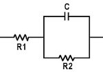
In fact the equivalent passive equivalent circuit of the capacitor is the same model as the battery.
image.jpg
The series resistance, R1 of a lead acid battery tends to be much lower than a capacitor. But when connected to long inductive or resistive leads, thus capacitors should be located closest to the load, is used are more effective than directly across the battery. When it is battery ESR issue, the capacitor should be closest to the battery.

But if the load path length is short with very little inductance, the ripple may be reduced without any benefit from a capacitor. Thus it is the wire inductance that needs the filter more than the battery. However , short proximity may not be possible, so adding a low ESR is suggested.

Consider a flooded 12V lead acid with 100A ripple current causing 1V ripple voltage. Thus given ESR = 1V/100A=0.01 at 50 Hz. , where dt= 0.01s. To reduce the V-ripple to 0.1V would require an ESR of 0.001 and a capacitance of C=Ic*dt/dv=100A*0.01s/0.1V=
C=10 Farads
 
yeah well 10 F that big, and how are we going to make one with low ESR and
low inductance. better than a battery?
i agree there is relay no point putting a capacitor directly across a battery
that can supply 100A. or even 380A pulse current like a car battery can.
if the battery gets killed is normally because of distorted plates. or furred up plates
because you will need some very large capacitors to make any difference and the
cost and size far out way the provision of a larger battery.
but yeah if one wants to spend the money caps may be beneficial at the invertor input especially if its a switcher, the run time before the inverter gives up may be longer, especially when the battery is getting old and the ESR starts to increase
however the extra capacitors will not be wort the effort and costs.
 

however the extra capacitors will not be wort the effort and costs.
I was primarly thinkink about pwm frequent ripple which can be fairly good filtered. Buit I see that in case of a single phase sine or "modified sine" inverter, 100 Hz ripple is much more difficult to handle.

In this relation, I agree that passing most of the ripple current to the battery may be a reasonable compromise, although the overall efficieny will be reduced, particularly with a small battery respectively > 0.5 CA discharge speed.
 

If you regard a battery as a distributed line of series inductance and parallel capacitance, then at any frequency the internal current distribution will not be equal (either on charge - often neglected, or discharge). If you insist on taking the current out in short pulses, then the area nearest the terminals will be over exercised and remote areas might not be feeding any current at all. This will lead to the over exercised area "dying" so a slightly more remote part of the plates now supplies the current. For inverter fed batteries it is a common fault for short battery life. It is called "micro charging". Great big electrolytics must an advantage but I feel that you need to ensure that the current waveform propagates down the battery plates much slower then the physical distribution line dimensions would suggest. So high audio to low RF decoupling should be thought about (at the rated current!), i.e. a string of 1 MF polycarbonate capacitors.
Frank
 
Status
Not open for further replies.

Similar threads

Part and Inventory Search

Welcome to EDABoard.com

Sponsor

Back
Top