Axxel
Newbie level 3
Hi everybody :grin:
I´m Axel, French and living in Barcelona and I love electronics :lol:
:lol:
Sorry for my English I will try to explain it well ;-)
I searched for a solution during a lot of time and... I think I need a little bit of help...
I will try to explain you my problem.... :-?
I just made on my breadboard a RGB to PAL video encoder, it works very well on a CRT classic TV, but with a BT878 capture card, I see the picture but in B&W... And with a car DVD portable set with AV input, I can see only some parasites...
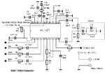
First I use a French/European Nintendo NES to get an RGB output. I extract the composite synchro with a LM1881 to enter into the MC1377 pal encoder, based en this scheme :
Here you can see a photo of the breadboard:
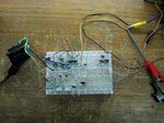
At the upper left, there is the MC1377 encoder, with a 3.58Mhz quartz to have an european PAL-BGHI output signal. I tried to amplify the output with a BF494C transistor and I get the same negative results.
At the upper right, there is a bands generator PIC based. (LINK -> https://www.edaboard.com/threads/4597/ ) In this case we won't use it because we are entering directly the RGB signal of the NES.
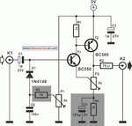
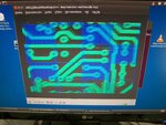
At the left down, there is another try of video amplifier, results to a fail too... This video amplifier use this scheme :
At the right down, there is the synchro-separator, based on LM1881:

Now the results in pictures: (The game is Megaman 4 and it is a very good game :wink: )
)
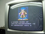
On the classic TV, perfect
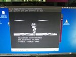
On the computer with a BT878, we loose the colour...
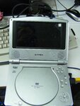
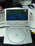
And on the car tv, only few white lines...
So, i tried to compare the output signal with a correct PAL signal. I use a SEGA Megadrive to do that.
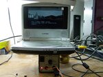
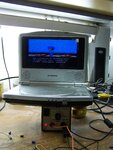
Now I make me sure everything is working correctly :

We can see everything working perfectly on the 3 devices.
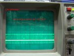
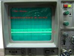
Now let's compare the output signal with oscilloscope:
MEGADRIVE OUTPUT : **broken link removed**
BREADBOARD OUTPUT : **broken link removed**
I see a difference of the middle continuous range of about 2 volts. So I think my signal is very high? Or is it the MC1377 that create this problem?
I tried to amplify o reduce the signal, without any positive results. Sometimes I can have some changes but I never get it working on the 3 devices...
Thanks a lot for reading me and for your attention :grin:
Cheers :grin:
Axel.
I´m Axel, French and living in Barcelona and I love electronics
Sorry for my English I will try to explain it well ;-)
I searched for a solution during a lot of time and... I think I need a little bit of help...
I will try to explain you my problem.... :-?
I just made on my breadboard a RGB to PAL video encoder, it works very well on a CRT classic TV, but with a BT878 capture card, I see the picture but in B&W... And with a car DVD portable set with AV input, I can see only some parasites...
First I use a French/European Nintendo NES to get an RGB output. I extract the composite synchro with a LM1881 to enter into the MC1377 pal encoder, based en this scheme :

Here you can see a photo of the breadboard:

At the upper left, there is the MC1377 encoder, with a 3.58Mhz quartz to have an european PAL-BGHI output signal. I tried to amplify the output with a BF494C transistor and I get the same negative results.
At the upper right, there is a bands generator PIC based. (LINK -> https://www.edaboard.com/threads/4597/ ) In this case we won't use it because we are entering directly the RGB signal of the NES.
At the left down, there is another try of video amplifier, results to a fail too... This video amplifier use this scheme :

At the right down, there is the synchro-separator, based on LM1881:

Now the results in pictures: (The game is Megaman 4 and it is a very good game :wink:
On the classic TV, perfect

On the computer with a BT878, we loose the colour...

And on the car tv, only few white lines...

So, i tried to compare the output signal with a correct PAL signal. I use a SEGA Megadrive to do that.
Now I make me sure everything is working correctly :


We can see everything working perfectly on the 3 devices.
Now let's compare the output signal with oscilloscope:
MEGADRIVE OUTPUT : **broken link removed**
BREADBOARD OUTPUT : **broken link removed**
I see a difference of the middle continuous range of about 2 volts. So I think my signal is very high? Or is it the MC1377 that create this problem?
I tried to amplify o reduce the signal, without any positive results. Sometimes I can have some changes but I never get it working on the 3 devices...
Thanks a lot for reading me and for your attention :grin:
Cheers :grin:
Axel.


