Continue to Site

Welcome to EDAboard.com

Welcome to our site! EDAboard.com is an international Electronics Discussion Forum focused on EDA software, circuits, schematics, books, theory, papers, asic, pld, 8051, DSP, Network, RF, Analog Design, PCB, Service Manuals... and a whole lot more! To participate you need to register. Registration is free. Click here to register now.

RF2638 as a BPSK modulator

Status
Not open for further replies.

obinobi

Junior Member level 3
Joined
Jan 17, 2009
Messages
27
Helped
1
Reputation
2
Reaction score
0
Trophy points
1,281
Location
Poland
Activity points
1,462
Hi
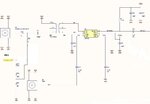
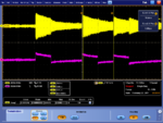
I would like to ask about implementation of RF2638 as a direct BPSK modulator. I see following problem - my output signal looks like ASK modulated signal not BPSK. Rectangular wave is connected to RF2638 through transformer. Any hints?

Best regards
 

Hi
I have attached schematic. The C9 is 10 nF. My IF rectangular wave is distorted a little bit. But it is not source of problem. The IF is driven by FPGA port. The series resistors have 1kOhm.

Best regards
 

Attachments

  • RF2638.JPG
    RF2638.JPG
    43.5 KB · Views: 105
Last edited:

TRy changing c9 to 0.1 uf and see if it starts to work. I assume the data is coming thru the coax connector and NOT thru the pin marked PRN (which has too much series resistance in that path).
 

Hi
Thank you for response. Data is comming through PRN pin connected to FPGA. Coaxial connector is for test purpose only.
I was trying to add series resistor (about 100 Ohm) between C9 and transformer to decrease rise/fall time of the current - remove distortion of rectangular wave. But it doesn't help.
It looks that output wave don't change phase but amplitude only because voltage between IF pins is not bipolar signal. I need to check this using differential probe.

You wrote that resistance in path between PRN and transformer is too big. Do you have suggestion how to resolve this problem? Using op amp?


Best regards
 
Last edited:

If R93 and R94 are really 10 K each, that is probably around 100x too large. What exactly are you trying to do?
 

Hi
These resistors are 1kOhm not 10k as is on schematic. They role is to decrease voltage level from FPGA (3.3V logic) to smaller value acceptable by RF2638. FPGA works as a PRN generator. I didn't find any details in datasheet what is acceptable level for IF pins but I suppose it is +3 dBm (absolute maximum ratings).
 

What's your FPGA output port impedance?
If it's 50R, change R93 and R94 to 0R.
If it's high impedance, change R93 and R94 to 0R, and change shunt 1K to 51R.
Just try.
Good luck.
 

The data sheet does not say. You DO want a differential swing on the two IF pins, so the transformer is correct to have. Also, you are floating the DC like they seem to show in the data sheet.

They are also not very clear about exactly what is inside of the mixer! If we assumed there were schottky diodes there, then you would need at least 2 diode drops to fully turn on the quad. that would mean 2x0.4 v = 0.8 volts differential ( or +/- 0.4 volts if you prefer).

However, it seems to imply that there is some sort of DC bias on the IF pins, so maybe it is a transistor or a fet you are trying to turn on.

They do mention something about a 260 ohm impedance, so if you stay below 5.2 volts differential, you will be limited to at most 20 ma, which is probably not enough to blow out the chip.
 
  • Like
Reactions: obinobi

    obinobi

    Points: 2
    Helpful Answer Positive Rating
Hi
I have asked RFMD about acceptable voltage level. In case of single ended signal (IF- AC grounded through 1nF) safe voltage is close to Vcc (+3.0 V).Higher will damage the IC.
Regarding transformer I think I have to remove him. Voltage on coil is equal:

U=L x di/dt

So in case of rectangular wave on FPGA output fast changes of current are seen as on waveform below. Yellow is RF signal envelope and pink is PRN code on RF2638 input.

https://obrazki.elektroda.pl/27_1299533725.png

I was trying to drive such transformer from DAC output (samples create a rectangular wave) and it looks exactly the same.
 

Attachments

  • CH3_in_CH1_RFOUT.png
    CH3_in_CH1_RFOUT.png
    107.6 KB · Views: 93

Status
Not open for further replies.

Part and Inventory Search

Welcome to EDABoard.com

Sponsor

Back
Top