Continue to Site

Welcome to EDAboard.com

Welcome to our site! EDAboard.com is an international Electronics Discussion Forum focused on EDA software, circuits, schematics, books, theory, papers, asic, pld, 8051, DSP, Network, RF, Analog Design, PCB, Service Manuals... and a whole lot more! To participate you need to register. Registration is free. Click here to register now.

RF TX as a HV generator measuring the current

Status
Not open for further replies.

neazoi

Advanced Member level 6
Joined
Jan 5, 2008
Messages
4,123
Helped
13
Reputation
26
Reaction score
15
Trophy points
1,318
Location
Greece
Activity points
36,955
Hi, this self-exited oscillator attached, is a redrawn version of this **broken link removed** including some modifications.
I noticed that the primary of the transformer has a very high RF voltage at one side, which is expected.

A crazy thought I am interested in, is using this thing as a HV generator for powering up small tubes. In contrast to mains frequency inverters, this works on RF.
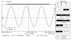
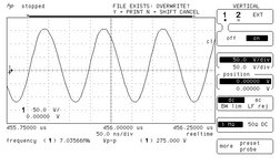
Now, I have measured the unloaded voltage and it is much more than 250v (the limit of my scope) and the waveform is a nice looking sinewave.

So I would like to find out how can I measure the current capability of the HV that it can provide, so I know what tubes can I power up with this thing. The oscillator draws 500mA-1A depending on the setting, at 24v.

Any ideas?
 

Attachments

  • sv3ora TX.GIF
    sv3ora TX.GIF
    2.9 KB · Views: 82
Last edited:

(1A * 24V) = your current * your voltage * (efficiency% / 100).

Assume 50% efficiency to be realistic but consider that the rectifier must be able to carry (2 * peak voltage) at the frequency of oscillation. Finding a fast enough power diode might be a problem.

Brian.
 

    neazoi

    Points: 2
    Helpful Answer Positive Rating
(1A * 24V) = your current * your voltage * (efficiency% / 100).

Assume 50% efficiency to be realistic but consider that the rectifier must be able to carry (2 * peak voltage) at the frequency of oscillation. Finding a fast enough power diode might be a problem.

Brian.
I might use self rectification in the tube, i.e connect directly the HF to the anode and have the tube operate at half the cycle
 

What's your frequency and load ? If you are able to measure the Loaded Voltage, you can also measure the Power by a Power Meter.
So, the Current will be available..
 

What's your frequency and load ? If you are able to measure the Loaded Voltage, you can also measure the Power by a Power Meter.
So, the Current will be available..
The frequency can be anything from 3.5 to 10MHz. Let's say 7MHz as an example.
The problem is that I do not know what the load will be (i.e the anode of the tube type that this circuit would be connected). I need to determine the current capability on different loads I guess. Moreover, I think I will try self rectification in the tube that will be driven by this circuit, i.e work the tube only on the positive cycle. This is just an idea which I do not know if it will work.
Would that be practical to place resistors of different values from the HV point to the ground and then measure the voltage across them? (and hence the voltage drop under this load)
 

I have placed a resistor from the top of the LC and measured the voltage across the scope.
Here are the Vpp measurements for 15k (300Vpp) and 5k 275Vpp) resistors.
I could not go much lower in load resistance because it was getting hot from the DC of the PSU.
The output power of the transmitter was still 5w (with the 15k resistor in place) and 4w (with the 5k resistor in place).

Does this give you any hint if this thing can provide something like 70-100mA at around 300v for driving a tube plate?
And to be more specific I am thinking to feed this circuit with it https://www.glowbugs.info/2010/06/6n7-tube-qrp-power-amplifier-one-rainy.html
 

Attachments

  • 15k_load_5w.jpg
    15k_load_5w.jpg
    50.8 KB · Views: 77
  • 5k_load_4w.jpg
    5k_load_4w.jpg
    53.1 KB · Views: 71
Last edited:

You'll need at least 20W Power Source but this circuit gives you max. 1.89W ( according to your measurements )
You have to increase the Available Power.
 

Status
Not open for further replies.

Part and Inventory Search

Welcome to EDABoard.com

Sponsor

Back
Top