Continue to Site

Welcome to EDAboard.com

Welcome to our site! EDAboard.com is an international Electronics Discussion Forum focused on EDA software, circuits, schematics, books, theory, papers, asic, pld, 8051, DSP, Network, RF, Analog Design, PCB, Service Manuals... and a whole lot more! To participate you need to register. Registration is free. Click here to register now.

RF receiver bothered by high current flows

Status
Not open for further replies.

Tricka90

Member level 1
Member level 1
Joined
Sep 2, 2013
Messages
40
Helped
1
Reputation
2
Reaction score
1
Trophy points
8
Visit site
Activity points
385
I built a very simple circuit consisting in a RF transmitter / receiver, a PIC microcontroller, a Fan and a little LED Lamp. Pressing a button on a RF transmitter I can turn on and off the Fan or the Lamp.
The all circuit is powered by a 5V - 3A power supply.
In the link below you can see the RF transmitter / receiver modules:
https://forum.hobbycomponents.com/viewtopic.php?f=25&t=1324

That's how the Lamp is powered (the Fan is powered the exact same way):
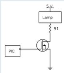
Wand Lamp.jpg

The R1 resistor is used to limit the current through the Lamp / Fan.

The circuit does work perfectly! The problem is I can't improve it: I'd like to decrese R1 value both on the Fan and the Lamp so they can work better. The problem is, the more current the two loads absorb, the more dirty and imprecise the receiver output signal becomes! I measured it with my oscilloscope and it's obvious that when I decrese R1 the signal gets a lot of interferences so the PIC can't read it correctly.

I tried connecting some capacitor here and there but it didn't solve anything. It even becomes worse with big capacitor values!
Now the Lamp and Fan absorbs only 200mA each, that's pretty low.

Do you have any solution for letting the Lamp and Fan absorb more current while keeping the receiver output signal as clean as possible?
 

I built a very simple circuit consisting in a RF transmitter / receiver, a PIC microcontroller, a Fan and a little LED Lamp. Pressing a button on a RF transmitter I can turn on and off the Fan or the Lamp.
The all circuit is powered by a 5V - 3A power supply.
In the link below you can see the RF transmitter / receiver modules:
https://forum.hobbycomponents.com/viewtopic.php?f=25&t=1324

That's how the Lamp is powered (the Fan is powered the exact same way):
View attachment 111813

The R1 resistor is used to limit the current through the Lamp / Fan.

The circuit does work perfectly! The problem is I can't improve it: I'd like to decrese R1 value both on the Fan and the Lamp so they can work better. The problem is, the more current the two loads absorb, the more dirty and imprecise the receiver output signal becomes! I measured it with my oscilloscope and it's obvious that when I decrese R1 the signal gets a lot of interferences so the PIC can't read it correctly.

I tried connecting some capacitor here and there but it didn't solve anything. It even becomes worse with big capacitor values!
Now the Lamp and Fan absorbs only 200mA each, that's pretty low.

Do you have any solution for letting the Lamp and Fan absorb more current while keeping the receiver output signal as clean as possible?

This problem often happens due to powering the RF sensitive receiver from a common supply which ALSO power the power loads.
The solution is to separate the DC power circuits. Use one DC supply ONLY for the RF board (you can use a battery,too) and the other ONLY for high-power load like LEDs and fans.

You can also separate both boards by better DC filtering. LED and fan drivers and uCs often generate interference which enters the RF board. Try a metal case for the RF board, separate the antenna as far as possible from the loads. Use screened wiring.
 

Yes, I also found that soultion!
I tried to power the RF receiver using a different power supply, that way I can give the Lamp and the Fan a lot of current and the receiver output signal stays perfectly clean!
The problem is I'd like to power all the circuit using the same power supply. Is it possible to solve the problem just by doing some changes in the circuit?
I'll try as soon as possible the metal case solution.

Thank's a lot for the help!
 

yeah, since the pic draws so little current,power it thru a 100 ohm series resistor, then a 47 uF cap right next to the chip.
 

The lamp only draws a DC current, so if this on its own causes the pic to misbehave it must be because the supply volts are dropping. The fan may contain its own oscillator, so it takes current in pulses from the Vcc, so a big capacitor across the fan, should then turn the transistor current into a pure DC, then it will act like the lamp.
Frank
 

If the power supply is 5v and your module allows for 3.3v operation, you can add a 3.3v LDO regulator with few caps and run the RF module and the PIC (most PICs either have a LF series for the same model or allow you to run them at lower voltage if you lower the clock) at 3.3v.

If 3.3v operation is feasible separate the main PS and the LDO by a blocking diode and large capacitor.
 

Status
Not open for further replies.

Similar threads

Part and Inventory Search

Welcome to EDABoard.com

Sponsor

Back
Top