Continue to Site

Welcome to EDAboard.com

Welcome to our site! EDAboard.com is an international Electronics Discussion Forum focused on EDA software, circuits, schematics, books, theory, papers, asic, pld, 8051, DSP, Network, RF, Analog Design, PCB, Service Manuals... and a whole lot more! To participate you need to register. Registration is free. Click here to register now.

RF Limiter Simulation in ADS

Status
Not open for further replies.

wwshr87

Newbie level 3
Joined
Apr 3, 2020
Messages
3
Helped
0
Reputation
0
Reaction score
0
Trophy points
1
Activity points
29
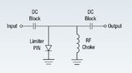
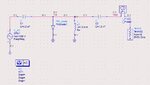
I'm trying to simulate a single stage RF limiter in ADS using the PIN_diode model. I have attached the topology that shows up on the PIN diode (CLA4601) limiter schematic. I would expect that as the input power increases at some power level it will start limiting. However, I'm always getting Pout=Pin.
I suspect the PIN diode is not self biasing as it should. If I use a DC bias on the diode it will limit the output power as expect. If someone can explain what concept I'm missing here.

Thanks!
 

Attachments

  • RF Limiter_1.JPG
    RF Limiter_1.JPG
    20.5 KB · Views: 623
  • RF Limiter_2.JPG
    RF Limiter_2.JPG
    74.2 KB · Views: 772

Thank you for the suggestion. I used large signal analysis (LSSP) and RF Limiter is working as expected.
 

Do you have a reference I can read that explains the different simulations in ADS and when to use them? I bought the book "RF and Microwave Circuit Design: Updated and Revised with 100 Keysight (ADS) Workspaces", I think that would be a good reference. Also, any good books about RF design in general.

Thanks!
 

Status
Not open for further replies.

Part and Inventory Search

Welcome to EDABoard.com

Sponsor

Back
Top