Continue to Site

Welcome to EDAboard.com

Welcome to our site! EDAboard.com is an international Electronics Discussion Forum focused on EDA software, circuits, schematics, books, theory, papers, asic, pld, 8051, DSP, Network, RF, Analog Design, PCB, Service Manuals... and a whole lot more! To participate you need to register. Registration is free. Click here to register now.

RF Choke operated above SRF

Status
Not open for further replies.

ah.vinod

Junior Member level 2
Joined
Apr 12, 2010
Messages
20
Helped
0
Reputation
0
Reaction score
0
Trophy points
1,281
Location
India
Activity points
1,436
In RF designs, why should a Inductor should not be operated above SRF region even though just above SRF the impedance is still High. I am looking for RF choke application used in typical LNA MMIC. i am using 1 uH inductor whose SRF is 400MHz while my frequency of operation of LNA is 40MHz to 860MHz. Untill 860MHz the RF Choke or inductor is having Impedance in Kilo Ohms. so can i go ahead and use it. attachment shows my application circuit
 

why should a Inductor should not be operated above SRF region
It's just a rule of thumb. You showed, that it's not absolutely correct. But I guess, you didn't find a reference for "even though"...
 

Hi,

Can u please provide a reference for "even though" case as it will help me better understand inductor and take a better decision.

Regards
Vinod A H
 

I don't know any. Obviously you don't have inductive behaviour above SRF. But it doesn't matter for a DC bias circuit.
 

Maybe this might help. It shows the effect on signal and phase of a simple inductor with two different source resistors 10k and 50 ohms. The peaky nature of the resonance is damped by the 50 ohm source so the impedance plateaus. The corner frequency of the plateau is actually where the inductive reactance is 50 ohms rather than anything due to the parallel capacitance.

Keith.
 

Yes, the pole at 21 GHz is above the shown frequency range.
 

In these cases, you can put two inductors in series, say a 1 uh and a 22 nh, maybe with a few ohm resistor in between to quell any resonance.

They do make inductors that are conical shaped that will do ultrawideband without resonance.
 
  • Like
Reactions: ferdem

    ferdem

    Points: 2
    Helpful Answer Positive Rating
The RFMD application schematic goes up to 200MHz using 10uH. You probably have to use a smaller inductor value to get a higher self resonant frequency.

I don't believe the application schematic uses the inductor to resonate out any capacitances that are hanging on the RFout pin. It creates high impedance at your operating frequency. Going past the self resonance defeats that purpose and is probably not a well controlled effect either. But, if it works well enough for your purpose, congratulations!

Maybe consider removing Rbias. It lowers your DC current and lowers your gm.
 

snafflekid said:
It creates high impedance at your operating frequency. Going past the self resonance defeats that purpose and is probably not a well controlled effect either.

Is that really true? The impedance above resonance is still kilo ohms. The difference is it is capacitive instead of inductive.

Keith
 

Hi all,

Can a Ferrite bead be used as RF Choke instead of inductor being used as RF Choke in LNA Biasing circuit. i am able to find Ferrite bead which suits my application. so only i am asking.

Regards
Vinod
 

keith1200rs said:
snafflekid said:
It creates high impedance at your operating frequency. Going past the self resonance defeats that purpose and is probably not a well controlled effect either.

Is that really true? The impedance above resonance is still kilo ohms. The difference is it is capacitive instead of inductive.

Keith

Well, I mean that the impedance is going to drop as the frequency increases, but if you are satisfied with the amount of impedance above the self resonance, good enough.

As for the capacitive load, I'm not sure of the effect. As you know, in a feedback system a capacitive load can start to drop the phase around the unity gain frequency and affect stability. But in an LNA you try to eliminate feedback altogether by cascoding (feedback would be unintentionally through the Cgd) So I suspect any capacitance on the output would be the dominant pole, since the unity gain frequency would be the transit frequency wt=gm/Cgs

I am no expert in stability analysis of RF circuits. I wish I was!
 

Hi,

I used the coil inductor for Amp Bias circuits even at 4GHz, the important is the package should be 0603. For freq higher than 4G, I used microstrip high impedance stub for bias.
 

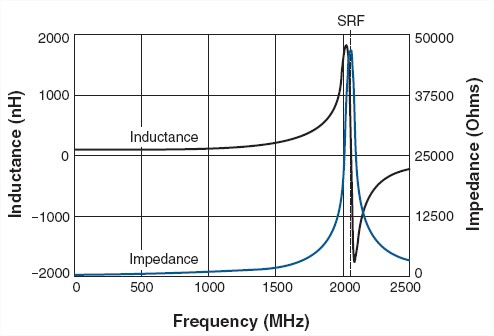
SRF is defined by the equation: SFR=1/(2*Sqrt(L*C))

For choke applications, the SRF is the frequency that provides the best signal blocking. At frequencies below the SRF, impedance increases with frequency. At the SRF, impedance is at its maximum. At frequencies above the SRF, impedance decreases with frequency.

In general, the choice of inductance value typically determines the SRF and vice versa. The higher the inductance value, the lower the SRF, due to increased winding capacitance.

Inductance and impedance rise sharply near an inductor’s self resonant frequency (SRF). For choking applications, chose an inductor whose SRF is at or near the frequency to be attenuated. For other applications, the SRF should be at least 10 times higher than the operating frequency.

49_1282376500.jpg
 

David.D said:
Inductance and impedance rise sharply near an inductor’s self resonant frequency (SRF). For choking applications, chose an inductor whose SRF is at or near the frequency to be attenuated. For other applications, the SRF should be at least 10 times higher than the operating frequency.

This sound sense in theoretically, BUT in real life it is difficult.
1. How about the SRF yield tolerance?
2. How about the cost and order period?
 

Status
Not open for further replies.

Part and Inventory Search

Welcome to EDABoard.com

Sponsor

Back
Top