Continue to Site

Welcome to EDAboard.com

Welcome to our site! EDAboard.com is an international Electronics Discussion Forum focused on EDA software, circuits, schematics, books, theory, papers, asic, pld, 8051, DSP, Network, RF, Analog Design, PCB, Service Manuals... and a whole lot more! To participate you need to register. Registration is free. Click here to register now.

RF attenuators in mixer's input port

Status
Not open for further replies.

Fovakis

Member level 5
Joined
Nov 15, 2012
Messages
88
Helped
1
Reputation
2
Reaction score
1
Trophy points
1,288
Location
Greece,Athens
Activity points
2,028
Hi ! I am making an RF Transmitter and i have a problem with power leakage for LO port to IF port and RF port. I don't know what to do and i am little confused about how can i fix this.


Source(-10 or -20dBm) 10KHz --------->MIxer conv.loss=8db--------->RF port
and
L.O=70MHz and 7dbm

I put an oscilloscope to mixers input IF and i don't see a sin wave from my Source.it is a sine wave with a lot of phase noice and amplitude variations..when i decrease the L.O power the sine becomes better.

I have heard about attenuators but i cannot understand how they will solve the problem. They attenuate maybe the standing waves that maybe create ?Also and my signal right?
 

The expected output signal is a amplitude modulated waveform rather than a sine, with- or without carrier depending on the mixer type.
 

The LO leakage at the IF port can be easily filtered since the IF is 10 kHz and the LO is 70 MHz. You could build a low pass filter, or companies such as Mini-Circuits sell small connectorized or surface mount low pass filters. The attached is one that should work well for you. For best results put a small pad (~3 dB) between the mixer and the low pass filter.
 

Attachments

  • Mini-Circuits SLP-5.pdf
    126.2 KB · Views: 47

Most mixers generate many unwanted frequency combinations. You must use filters to get only the wanted ones. If LO leaks to IF or RF, filters must get rid of the leakage.
 

The LO leakage at the IF port can be easily filtered since the IF is 10 kHz and the LO is 70 MHz. You could build a low pass filter, or companies such as Mini-Circuits sell small connectorized or surface mount low pass filters. The attached is one that should work well for you. For best results put a small pad (~3 dB) between the mixer and the low pass filter.

Hi my friend and thanks for your reply. So the high frequency of 70MHz is inserting to IF port right? So i must cut these 70 MHz...

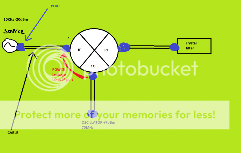
But, these leakage of power is between the ports how can i cut it? See my image below.
[URL=https://s1284.photobucket.com/user/fovos1/media/PowerleakageLotoIF_zps53337d72.png.html][/URL]

If the high frequency was producted from the generator and were unwanted, i understand that i must put a LPF as you said to cut them.
But from Lo port to IF port the filter is prior to IF port how can it stop the unwanted freq?

This is my mixer:**broken link removed**

The RF VSWR is good . The LO VSWR is 2.5:1 so if it needs 7dBm i put 8dBm and i am ok. But the IF VSWR needs some matching right?>

WHat about this pad :**broken link removed** to put between 10khz generator and IF port. 1 dB loss only
 
Last edited:

That is the LO leaks to RF port, not IF port.
 

If you are using a Minicircuits ZAD-6 level 7 mixer then it should give about 35dB port isolation from LO to IF at 70MHz and a bit less at 140MHz.

So with +7dBm LO you would normally get about -28dBm LO power leaking to the IF port from the 70MHz LO port. You will also get some leakage at 140MHz and higher harmonics. Also you will see some reflected energy from the unwanted image term that is rejected and reflected back from the crystal filter.

If you are only putting in -20dBm at 10kHz at the IF port then the scope will show a very fuzzy looking sine wave at 10kHz because the leaked -28dBm LO signal at 70MHz (and its harmonics) will interfere with it as it is only about 8dB lower than the -20dBm 10kHz signal at the IF port. The fuzziness is caused by the 70MHz LO signal + harmonics riding along with the 10kHz signal with an amplitude of roughly a third of the 10kHz signal. This makes the 10kHz signal look like it has fuzzy interference on its peaks on a scope.

Usually this isn't a problem unless the 70MHz/140MHz LO energy can leak further back into the circuitry that drives the IF port and cause interference/distortion products.

If this is a problem then try a ZAD-3 mixer instead because it has about 10dB better port isolation at 70MHz.

You could also try driving the IF port with a stage that has high reverse isolation if you are worried about the leakage terms causing interference/distortion in the IF drive stage. Also, it generally isn't a good idea to put a crystal filter directly at the RF port because you will degrade the IMD performance of the mixer due to the image being reflected back into the mixer.
 
Last edited:

Hi my friend. Can i use a LPF between 10KHz generator and first mixer ? check my image above please.

*the image frequency of the mixer ouput is the 3rd order etc right? so i must put a pad between crustal filter and mixer?
 

Hi my friend. Can i use a LPF between 10KHz generator and first mixer ? check my image above please.

*the image frequency of the mixer ouput is the 3rd order etc right? so i must put a pad between crustal filter and mixer?

Yes you can put the LPF between the signal source and the mixer. The pad should go between the mixer and the LPF.

Generally, you will see better performance if your put a pad between a mixer and filter. Spec sheets for mixers and filters always assume a broadband 50 ohm match, and if your implementation does not provide a broadband 50 ohm match, then your performance will probably be worse than the datasheet specs. The pad will provide a broadband 50 ohm impedance and it will also help to absorb some of the energy the filter is reflecting.
 

How can i understand that i don't have good matching between mixer and crystal filter. From datasheet i see LO at 30MHz VSWR=1.18 . About the crustal filter i only know that is has 50 ohm impedance.

I understand if i don't have good isolation to put a LPF ok. But i don't understand how i can be sure that i need a pad? only from datasheet's VSWR?
 

An RF filter works by reflecting signals outside of the passband, and this reflection is caused by an impedance mismatch. So in the passband the filter's impedance is 50 ohm and the signal does not see an impedance mismatch and goes through with just a little attenuation. In the stopband though the filter's impedance is either close to 0 ohms or close to infinity depending on the filter structure. A 50 ohm signal in the stopband sees a large impedance mismatch and is reflected. The crystal filter only presents a 50 ohm impedance to the mixer in the passband, at all other frequencies it presents a very poor impedance match.
 

the reflected from stopband frequencies finally where are they going? they are going to rf port then intermodulate with LO port and they output at the If port ? so i need pads to cut these reflections. So a pad can cut signals powers with two directions. Input to Output and Ouput to input. Incidents and reflected

But about the leakage of 30 or 70MHz of LO to IF port... IF signal is 10khz...tha leakage will be 30 or 70MHz..is there so much problem?it is -28dBm leakage to IF port and my signal is -20 dBm but they are so far frequencies? why problem?
 
Last edited:

Yes, that is exactly correct. The reflected signal will go back into the mixer and can create other spurious products. The 3 dB pad actually attenuates signals in the stopband by 6 dB since they go through the pad twice, once in the forward direction, once as a reflection. Usually this is enough, but you may also want to experiment with larger pad values.

As for leakage in the IF path, that is going to be dependent on the signal generator. Does the signal generator become unstable with this power coming into it? Does the signal generator provide a broadband match (absorb this power) or is it a poor match at these frequencies and reflect that power back into the mixer? Answering these questions is probably easiest with some experimentation in the lab.
 

The mixer has isolation specifications and the first simple question is: is it sufficient for your application? You should consider that the specification presumes 50 ohm termination of all ports, it's probably not achieved "naturally" for the low frequency IF port.

I don't see how reflecting part of the leakage power back to the port would generate new frequency components that aren't already present at all ports before. But of course it will slightly change the level of wanted and unwanted signals at the other ports.
 

Yes, that is exactly correct. The reflected signal will go back into the mixer and can create other spurious products. The 3 dB pad actually attenuates signals in the stopband by 6 dB since they go through the pad twice, once in the forward direction, once as a reflection. Usually this is enough, but you may also want to experiment with larger pad values.

Many thanks for your kind reply. So for example my mixer RF port has VSWR=3:1 (Preflect=30%) and next component is a filter with VSWR=1.5 (Preflect=4%).
I read that the total VSWR is 4.5:1 so ~Pref=40%. It is seems to me not right. For example. I have 1 watt signal at RF port. the reflected is 0.25watt. transmitted is 0.75 watt. then at filter the relfected=0,75*0,04=0,03watts. so total reflect signal to 1 watt is 0,28 watt .that is not VSWR 4.5

So a pad can remove the unwanted reflected waves that can cause problems to my device. that's what i understand

- - - Updated - - -

I don't see how reflecting part of the leakage power back to the port would generate new frequency components that aren't already present at all ports before. But of course it will slightly change the level of wanted and unwanted signals at the other ports.

I don't understand what do you mean here dear FvM..
 

Status
Not open for further replies.

Similar threads

Part and Inventory Search

Welcome to EDABoard.com

Sponsor

Back
Top