Continue to Site

Welcome to EDAboard.com

Welcome to our site! EDAboard.com is an international Electronics Discussion Forum focused on EDA software, circuits, schematics, books, theory, papers, asic, pld, 8051, DSP, Network, RF, Analog Design, PCB, Service Manuals... and a whole lot more! To participate you need to register. Registration is free. Click here to register now.

RF Amplifier not amplifying signal

Status
Not open for further replies.

LandLack

Member level 3
Member level 3
Joined
Aug 8, 2013
Messages
54
Helped
1
Reputation
2
Reaction score
1
Trophy points
8
Visit site
Activity points
526
Hi, I don't understand something about the amplifiers I'm using during my simulations with ADS; my circuit has a square signal which has been previously upconverted to 410MHz. I need to amplify this signal from -20 dbm to near 0dbm, so I use an amplifier. After the simulation, with "Harmonic Balance" (power amplitude-frequency) I see that the signal has really been amplified by about 18 dB (to -2.1dBm), but when I see the "Transient" result it is displayed that the amplitude of the voltage hasn't changed (it seems to have been decreased from 31mV to 27mV). Shouldn't power be (V^2)/R? Why can't I see a voltage amplification of (about) 10 if the power has been amplified by (about) 100 times?

Since the harmonic balance seems to confirm the datasheet values, I don't think that something in my schematic was wrong. I'm giving you the graphs obtained in an attached image.amplimm.png AmplImm.png
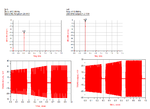
 

An upconverted "square" signal will create a spectrum with two side bands. One should be rejected by a filter. Your "simulation" makes no sense at 410 MHz.
 

An upconverted "square" signal will create a spectrum with two side bands. One should be rejected by a filter. Your "simulation" makes no sense at 410 MHz.[/QUOTE


This is a "Harmonic Balance" simulation, and does not show the entire frequency spectrum, but only an impulse with the power amplitude value on the carrier frequency; Agilent ADS doesn't give you the possibility to see the signal the usual way we are used to, probably because it requires too much computation. Here is the image of the schematic with the simulation tools: **broken link removed** .
The bias tee is needed to remove the DC signal from the output (and some other purposes), and doesn't interfere with frequencies higher than 50MHz (I have tried working without, but still had the same results. The 50ohm load replaces the next component.
While the frequency view may be misunderstood since it's unorthodox view, I can assure you that it's very dependable when you hame many tones; the transient view is the same as usual.
Here is a hint about Harmonic Balance: https://en.wikipedia.org/wiki/Harmonic_balance ;
 
  • Like
Reactions: wdwxn

    wdwxn

    Points: 2
    Helpful Answer Positive Rating
**broken link removed**
Sorry I had some difficulties in uploading the image
 

Like transistor, it,s the current that been amplified . not voltage.
 

Status
Not open for further replies.

Part and Inventory Search

Welcome to EDABoard.com

Sponsor

Back
Top