franticEB
Full Member level 3
Hi,
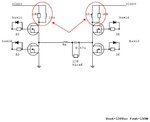
i've found an old inverter schematic with an inductor and resistor on high mosfets' drain as figure below

I try to reproduce it without RL circuit and mosfets become hot (80° over ambient) for conduction and switching losses as in my calculations.
Then i tried to mount the RL circuit and temperature rise on mosfets was very low (30° over ambient).
I did not understand how this circuit (RL red circle in figure) acts and how you can calculate component values.
Could you help me? I don't found anything (tutorial or application note on this subject).
This RL also allow me to increase switching frequency...
Parameters:
Fswitching=50Khz
Pout=150Wrms
i've found an old inverter schematic with an inductor and resistor on high mosfets' drain as figure below

I try to reproduce it without RL circuit and mosfets become hot (80° over ambient) for conduction and switching losses as in my calculations.
Then i tried to mount the RL circuit and temperature rise on mosfets was very low (30° over ambient).
I did not understand how this circuit (RL red circle in figure) acts and how you can calculate component values.
Could you help me? I don't found anything (tutorial or application note on this subject).
This RL also allow me to increase switching frequency...
Parameters:
Fswitching=50Khz
Pout=150Wrms