prabhukaran3
Member level 5
Hi guys,
Great evening to all.
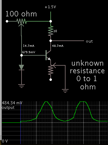
I need to measure resistance of a wire(Thick wire-resistance ~0.1-10E).... Since its very low resistance I cant develop circuits with voltage divider network and ADC... I google a week before but most of results based on Op amp(Strictly they advised to do not use LM324). Is there any simplest way to measure low resistance... Any one having working circuit for this?
Great evening to all.
I need to measure resistance of a wire(Thick wire-resistance ~0.1-10E).... Since its very low resistance I cant develop circuits with voltage divider network and ADC... I google a week before but most of results based on Op amp(Strictly they advised to do not use LM324). Is there any simplest way to measure low resistance... Any one having working circuit for this?
")