Continue to Site

Welcome to EDAboard.com

Welcome to our site! EDAboard.com is an international Electronics Discussion Forum focused on EDA software, circuits, schematics, books, theory, papers, asic, pld, 8051, DSP, Network, RF, Analog Design, PCB, Service Manuals... and a whole lot more! To participate you need to register. Registration is free. Click here to register now.

Replacement RF amplifier

Joined
Nov 20, 2023
Messages
2
Helped
0
Reputation
0
Reaction score
0
Trophy points
1
Activity points
34
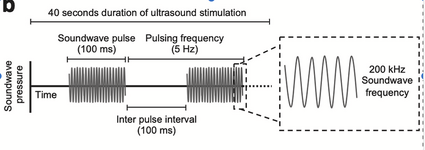
I am trying to generate 200 kHz pulsed ultrasound waves while changing other parameters (pulse repetition frequency between 5 Hz and 40Hz, duty cycle.).

I currently use a piezoelectric transducer to generate ultrasound. It is powered by a signal generator amplified by an RF amplifier. The signal is around 480 mVpp amplified to around 50 Vpp.

The expense of the RF amplifier is a rate-limiting step, so I need to find a cheaper alternative. I assume that should be possible as I only need a 200 kHz amplifier (that can accurately amplify the pulsed signal), but I am unsure where to start looking. Does anyone have any tips?
 
Hi,

so you want to generate wave packets of 200kHz pulses with a variable repitition rate and variable duty cycle.

I guess every Arduino hardware can do this for a couple of $.

Whether this is suitable for you depends on a lot of parameters / requirements.

You say "changing". But don´t say what this means.
Is it manually by adjusting a potentiometer, or using UP ad DOWN buttons, or via internet interface, IR remote ...? or just automatically
What range, what resolution?
Is it like a "gate" where the first and the last pulse might be incomplete, or do you always want an integer count of identical pulses?

Is "a wave" a 50% duty cycle square wave, or sine, or any other waveform?

I expect a simple sketch with an as complete as possible description of the pulses and the parameters.

Klaus
 
The Farnell Link is 404 (going nowhere like Hwy 404 in rushhour in TO.)

1700507296680.png

Ic= C dV/dt for C ~ 1nF , dV = 50V so Ic= 50 mA/us

Gain is 50V/0.5 = 100 min.

It needs to be low Q to turn off quickly. You can choose the driver impedance from V/Ic [max]

Now what have you learnt about high-gain , high-voltage high slew-rate amplifiers?
IGBT? Bipolar? FET?
--- Updated ---

If a design is difficult to create, you can choose to "buy" instead of "make".

You can use a much bigger piezo with this amp.

 
Last edited:
I'm using the same transducer in a doppler airspeed measurement system. Capacitance specification is misleading, it's a static parameter valid for f << fres. Like other resonant transducers, it shows adjacent series and parallel resonance points. Impedance in both resonance points is real.

Unfortunately I can't tell about continuous input power rating of the transducer. I doubt you can apply 500 Vpp in series resonance without breaking the piezo.

Using a MHz linear amplifier to drive the piezo is a costly choice. A square wave driver can do the job.
 
T
Hi,

so you want to generate wave packets of 200kHz pulses with a variable repitition rate and variable duty cycle.

I guess every Arduino hardware can do this for a couple of $.

Whether this is suitable for you depends on a lot of parameters / requirements.

You say "changing". But don´t say what this means.
Is it manually by adjusting a potentiometer, or using UP ad DOWN buttons, or via internet interface, IR remote ...? or just automatically
What range, what resolution?
Is it like a "gate" where the first and the last pulse might be incomplete, or do you always want an integer count of identical pulses?

Is "a wave" a 50% duty cycle square wave, or sine, or any other waveform?

I expect a simple sketch with an as complete as possible description of the pulses and the parameters.

Klaus
Thank you for your answer.

I was incorrect about varying the duty cycle - it is all run at 50% duty cycle.

We have four different settings, all at 200 kHz and the pulse repetition frequency (PRF) at either 5Hz, 20Hz, 40Hz and 80Hz. Importantly, the PRF is altered (up/down on our signal generator) before the sonication period/session begins and does not change during that session.

The first and last pulse can be incomplete, I guess it depends on how long the session lasts for.

The wave is sinusoidal.

Please let me know if you need any other information.
 

Attachments

  • Screenshot 2023-11-23 at 17.43.46.png
    Screenshot 2023-11-23 at 17.43.46.png
    199.9 KB · Views: 51
Last edited:
Hi,

now you say duty cycle is 50%. I don´t understand this, because:
* sinewave has no duty cycle at all
* and your gating is 100ms ON, the other time OFF, so not 50%.

**
If you want to send out gated sine packts ... and later process the data you shold know that non_zero_cross gated sinewave generates a lot of noise including DC offset.
So this may cause problems in overall precision.

***
A completely new situation. When I see "pulse" I think of a digital one, ON/OFF. like 0V/20V.
But now it´s sinewave. And the diagram shows aligned around zero (pso/neg) like +10V/-10V.

I said every Arduino hardware is able to generate the signal... but not as sinewave. In best case you could generate digital pulses and use a filter to get rid of the overtones. But it´s always a decision between filter effort and distortion, and transient behaviour.

I don´t think 200kHz is considered RF.
To look for a suitable amplifier you need to know:
* gain
* output voltage (undisorted sine)
* output current
* phase shift range of load (to ensure amplifier stability)
* allowable distortion
* additional information, like: power supply, efficiency, cost, size...

Klaus
 
Although 200 kHz is the specified frequency, your piezo transducer may lean toward its own individual frequency to resonate at (which may be identical or slightly different). You may be able to use this resonance to drive an oscillating circuit. A resistor generates voltage changes at precisely the moments when when current changes direction, causing the op amp to change state.

As shown in the simulation.
The low-ohm resistor is an added component. The series LC may represent the piezo's own resonant frequency, or the LC may be installed and adjusted to resonate at the preferred frequency, while also limiting current through the piezo.

op amp auto-detects LC resonant 200 kHz drives half-bridge 15V.png


A couple pf possibilities..

Note post #10 done to show easy generation of waveforms, burst, modulated, etc..
To show OP this is fairly simple to do with a single chip SOC and very little code.


Regards, Dana.


A couple pf possibilities..

Note post #10 done to show easy generation of waveforms, burst, modulated, etc..
To show OP this is fairly simple to do with a single chip SOC and very little code.


Regards, Dana.
The 1st choice is a good "Buy" option for this question or the PA98revT below.

This mighty Op Amp barely meets your requirements, even with these impressive specs.

High Voltage — 450V (±225V)
• High Slew Rate — 1000V/μs
• High Output Current — 200mA
1700939203047.png
1700937611765.png

1700938972259.png


@ 200 KHz , a half cycle = 2.5 us , Max dV into 900 pF with dt= 2.5 us @ 200 mA;
dV= 0.2A * 2.5 us / 0.9 nF = 555 V but that is over 100W and even with an infinite heat sink, the case Rth = 4.2 °C/W so a with 85'C max target at room temp a 60 'C rise limits power to 60/4.2 to 14 W or 71 V max. The curve above is shows a bit more must be verified and the x10 voltage gain still requires a pre-amp.
 
Of course two of these above in series may work, 1st for 10x gain.and BPF to make sinusoidal and 2nd to drive 250 mA into 900 pF at x1 gain preferably using +/-25V
--- Updated ---

Although 200 kHz is the specified frequency, your piezo transducer may lean toward its own individual frequency to resonate at (which may be identical or slightly different). You may be able to use this resonance to drive an oscillating circuit. A resistor generates voltage changes at precisely the moments when when current changes direction, causing the op amp to change state.

As shown in the simulation.
The low-ohm resistor is an added component. The series LC may represent the piezo's own resonant frequency, or the LC may be installed and adjusted to resonate at the preferred frequency, while also limiting current through the piezo.

View attachment 186392
Some improvements on output power gain and envelope risetime due to lowering high series Q and adding compensation voltage gain of 4 to 8 depending on Rs damping resistor.

But also significant power losses for every part to dampen the resonance. and bias the diodes with 4 mA. with hFE = 50 to drive 200 mApp to 400 mApp

1700953137430.png

--- Updated ---

360 Vpp with 270 ohm switch closed but longer envelope risetime
200 Vpp with " open..
Modulation switch is TBD.
--- Updated ---

cheaper than your Amplifier Research box, but more work.
 
Last edited:

LaTeX Commands Quick-Menu:

Part and Inventory Search

Welcome to EDABoard.com

Sponsor

Back
Top