Continue to Site

Welcome to EDAboard.com

Welcome to our site! EDAboard.com is an international Electronics Discussion Forum focused on EDA software, circuits, schematics, books, theory, papers, asic, pld, 8051, DSP, Network, RF, Analog Design, PCB, Service Manuals... and a whole lot more! To participate you need to register. Registration is free. Click here to register now.

Relations between Vref and LSB error of ADC?

Status
Not open for further replies.

Ma3ix

Member level 2
Joined
Dec 17, 2015
Messages
43
Helped
0
Reputation
0
Reaction score
0
Trophy points
6
Activity points
375
Hi,

can someone explain me relation between Vref vs LSB error cause Im a bit confused with datasheet of ADC.

Im using LM35 sensor for temperature measuring and ADC MCP 3004 for analog-digital conversion.
-------------
Vdd is 5V.

- if I use Vref = 5V then I dont have problems with LSB error, in other words readings from voltage instrument and display for temperature are coincides.
The problem is that I wanna better LSB size than 5/1024 ~ 0.5 mV which is 0.5 Celsius degress.

- when I decrease Vref than i have this results:

1) Vref = 1.307V; instrument reading :288mV; display reading: 298
This give me error of 1 Celsius degree. LSB size is 1.307V/1024= 1.276 mV so for 1 celsius degree I have to reduce output from ADC for about 8 LSB.


2) Vref = 0.933V; instrument reading :287mV; display reading: 317
This give me error of 3 Celsius degrees. LSB size is 0.933V/1024= 0.9 mV so for 3 celsius degree (317-287=30mV) I have to reduce output from ADC for about 33 LSB.


Is there a way to calculate / predict LSB error according to Vref value?

From diagram characteristics of MCP3004 for Vref around 1~1.5V should be about few LSB error? Or Im not reading correctly the datasheet.

ADC datasheet: https://www.microchip.com/wwwproducts/en/MCP3004
Thanks.
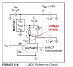
 

A promising way to increase the absolute ADC resolution is to use a precision amplifier in front of it instead of reducing Vref.

According to datasheet curves, you can however expect to almost keep the relative error down to 1-2 V Vref.
 

hello,

Your Vref are a bit strange !
usual value for Vref are 1,024V or 2,048V ...
any schematics and vref composant type ?
 

hello,

Your Vref are a bit strange !
usual value for Vref are 1,024V or 2,048V ...
any schematics and vref composant type ?

Why?
Usual value is an option, you just should not exceed min max value of Vref.

Im using simple voltage divider and voltage is stable.

- - - Updated - - -

A promising way to increase the absolute ADC resolution is to use a precision amplifier in front of it instead of reducing Vref.

According to datasheet curves, you can however expect to almost keep the relative error down to 1-2 V Vref.

I know, but according to datasheet curves I should expect less LSB error.. Even if you sum all the errors for Vref 1V it should be around 5 LSB?

So,it is not possible to calculate LSB error according to Vref using datasheet curves, only experimental?
 

Hi,

Im using simple voltage divider and voltage is stable.
A voltage divider as VRef is usually no goid idea.
Expect relatively high current peaks at VRef.

You should find information about this in the ADC datasheet.
I recommend an opamp as driver for VRef.
But if you insist on a voktage divider, then use a low ohmic one and add at least 1uF ceramcs capacitor next to VRef pin.

Additionally I don't recommend to use VCC or divided VCC as reference.
There are dedicated VRef ICs that are stable over time and temperature....especially in your case when you want to measure absolute voltages down to millivolts.

Klaus
 

Hi,


A voltage divider as VRef is usually no goid idea.
Expect relatively high current peaks at VRef.

You should find information about this in the ADC datasheet.
I recommend an opamp as driver for VRef.
But if you insist on a voktage divider, then use a low ohmic one and add at least 1uF ceramcs capacitor next to VRef pin.

Additionally I don't recommend to use VCC or divided VCC as reference.
There are dedicated VRef ICs that are stable over time and temperature....especially in your case when you want to measure absolute voltages down to millivolts.

Klaus

Vref current is about 0.2mA which should be fine?
Im using IC Vref and decreasing Vref with voltage divider and of course 1uF capacitor on Vref.


Low ohmic resistors?:?:
 
Last edited:

Hi,

can someone explain me relation between Vref vs LSB error cause Im a bit confused with datasheet of ADC.
I just opened the datasheet. It has a lot of charts:
* DNL vs VRef
* INL vs VRef
* Offset vs VRef
* gain vs VRef
* ENOB vs VRef
What else do you need?

"Any instability in the operation of the reference device will have a
direct effect on the operation of the A/D converter."

Did you follow the guidelines about analog input source resistance? (It will be worse with lower VRef)
Did you follow the layout guidelines? (Grounding, VCC, decoupling).
Don't try to test accuracy with a breadboard. The results tell nothing.


Expect relatively high current peaks at VRef.
You should find information about this in the ADC datasheet.

0.2mA may be the averaged current...it tells nothing about the peaks. Additionally I assume it depends on sampling frequency.

Low ohmic resistors:
(You don't tell what you currently use).

Klaus
 
  • Like
Reactions: Ma3ix

    Ma3ix

    Points: 2
    Helpful Answer Positive Rating
If I understand the post #1 results right, they are much worse than admitted by the datasheet. So there must be a problem with your circuit implementation. You also said to use suitable Vref bypassing, thus it must be something else, hard to tell from a distance.

I keep my previous comment that amplifying the input signal is probably the easier way to get better resolution and accuracy.
 
  • Like
Reactions: Ma3ix

    Ma3ix

    Points: 2
    Helpful Answer Positive Rating
Hi,


I just opened the datasheet. It has a lot of charts:
* DNL vs VRef
* INL vs VRef
* Offset vs VRef
* gain vs VRef
* ENOB vs VRef
What else do you need?

"Any instability in the operation of the reference device will have a
direct effect on the operation of the A/D converter."

Did you follow the guidelines about analog input source resistance? (It will be worse with lower VRef)
Did you follow the layout guidelines? (Grounding, VCC, decoupling).
Don't try to test accuracy with a breadboard. The results tell nothing.


0.2mA may be the averaged current...it tells nothing about the peaks. Additionally I assume it depends on sampling frequency.

Low ohmic resistors:
(You don't tell what you currently use).

Klaus

Hi and thanks.

I make mistake with capacitance near Vref, added just 0.1uF , with 1uF and specially 10uF I have much better results.
I have unstable Vref (about 0.005mV up/down) what is give me rapidly changing of the last digit value.
The problem can be in voltage divider and breadboard?
solution:
- move analog part from breadboard to pcb
- im using carbon resistors for voltage divide, metal-film should be better or some other?
 

Hi,

Capacitor: expectable

I have unstable Vref (about 0.005mV up/down)
0.005mV = 5uV = won´t harm you... but i rather think you mean 5mV. --> voltage divider

carbon/metal --> the value is more important here than the material. Metal are more precise.

Klaus
 
  • Like
Reactions: Ma3ix

    Ma3ix

    Points: 2
    Helpful Answer Positive Rating
Hi,

Capacitor: expectable


0.005mV = 5uV = won´t harm you... but i rather think you mean 5mV. --> voltage divider

carbon/metal --> the value is more important here than the material. Metal are more precise.

Klaus

You are correct as always, about 2~5mV unstable Vref.:thumbsup:

Im using Vref IC MCP1541 https://www.microchip.com/wwwproducts/en/MCP1541 and carbon resistors for voltage divider (33k + 10k) with 5%tolerance. According to datasheet figure 2-10, I should look for output current closer to 0 mA? (i have 4.096V/43K Ohms)
 

Hi,

I should look for output current closer to 0 mA? (i have 4.096V/43K Ohms)

wrong direction!
I recommended to use LOWER ohmic resistors.
Your Ref IC can drive up to 2mA. Go in 1mA direction.

Klaus
 

hello,


i get big problems with a Vref MCP1525 2,5V .. because i forget to put a capacitor of 1µF accross the output ...
without this , very big shift of voltage
it is specified in the MCP1541 Datasheet ..
 

I tried with 1uF and 10uF, still have unstable voltage for about 1-2mV.

My circuit looks like this:

vref.JPG
 

I agree with KlausST
divide by 10 your resistors dividor ...
3,3k + 1K
and not more than 1µF on output Vref
Tantale capacitor !

What is the noise on 5V power supply ?

you can not remove 1 or 2mV delta from your Vref..
or choose a better ref device.

at least you will have to average the MCU PIC measurement
with an exponential filter or a sliding window average
 

Hi,

You still refuse to accept that the adc needs a capacitor at it's vref pin.

Klaus
 

I agree with KlausST
divide by 10 your resistors dividor ...
3,3k + 1K
and not more than 1µF on output Vref
Tantale capacitor !

What is the noise on 5V power supply ?


you can not remove 1 or 2mV delta from your Vref..
or choose a better ref device.

at least you will have to average the MCU PIC measurement
with an exponential filter or a sliding window average

Thanks all for response

Power supply (usb) gives me 4.93~4.94V , 10mV up/down
Vref is now (with 1uF capacitor, i dont know type; I think is film capacitor ID:1uJ63) about 1mV up/down

- - - Updated - - -

Hi,

You still refuse to accept that the adc needs a capacitor at it's vref pin.

Klaus

I did now:thumbsup:

- - - Updated - - -

What can I still do?

1.) switch elements from BreadBoard to PCB
2.) software solution- after reading hold value for some period :/
 
Last edited:

Status
Not open for further replies.

Similar threads

Part and Inventory Search

Welcome to EDABoard.com

Sponsor

Back
Top