Continue to Site

Welcome to EDAboard.com

Welcome to our site! EDAboard.com is an international Electronics Discussion Forum focused on EDA software, circuits, schematics, books, theory, papers, asic, pld, 8051, DSP, Network, RF, Analog Design, PCB, Service Manuals... and a whole lot more! To participate you need to register. Registration is free. Click here to register now.

Regenerative receiver preamplifier voltage

Status
Not open for further replies.

neazoi

Advanced Member level 6
Joined
Jan 5, 2008
Messages
4,123
Helped
13
Reputation
26
Reaction score
15
Trophy points
1,318
Location
Greece
Activity points
36,955
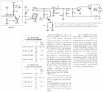
Hello I am trying to build this regenerative receiver which operates in 1.5v. The untuned RF preamplifier is from another regenerative circuit and operates on 9v. Can I make it operate on 1.5v as well by altering some components of it? I guess the gain should be limited of course.
 

Attachments

  • RX.gif
    RX.gif
    58.6 KB · Views: 69

You could try just dropping the 3.3K resistor to increase the current but to be honest with the collector and base DC tied together I wouldn't expect much gain, if any. A more conventional bias arrangement should work.

Brian.
 

You could try just dropping the 3.3K resistor to increase the current but to be honest with the collector and base DC tied together I wouldn't expect much gain, if any. A more conventional bias arrangement should work.

Brian.

What arrangement would you propose for a bias of 1.5v?
 

You can't easily change the RF preamplifier to run on 1.5V, but it's easy to change the regenerative receiver to run on 9V.

For the receiver part of the circuit, just replace the 10K resistor with a 150K resistor.

The audio amplifier part of the circuit (Q2, Q3 and the 1M resistor) is very bad though. I would recommend replacing it with a simple LM386-based amplifier.

edit: the receiver might actually work better if you leave the resistor at 10K. Try different values to see what works best - you can't damage anything.

On second thoughts, I suppose you could change the RF preamplifier to run on 1.5V - just replace the 3.3K resistor with a 270 Ohm one.
 
Last edited:

At the moment the base and collector are at the same DC potential which is not good in any amplifier. The configuration is common base which is good from an RF point of view but by the time the resistor values have been dropped and extra bias resistors added, any advantage it might have would be lost anyway.

Some experimentation is needed but my first guess at a solution would be to change the 3K3 resistor to say 270 Ohms and connect the antenna through the capacitor directly to the emitter. In the base, wire a resistor of 3K3 to ground and bypass it with a ceramic 10nF capacitor. Then wire the potentiometer as a variable resistor between the base and +1.5V line. In other words, alter the bias current to control the gain. It should allow you to set the current from zero to about 4mA, if necessary, add a resistor in series with the variable to prevent the bias being completely removed.

Brian.
 

Status
Not open for further replies.

Part and Inventory Search

Welcome to EDABoard.com

Sponsor

Back
Top