mike buba
Member level 2
Hi, I am trying to reduce switching noise in the MOSFET three-phase inverter.
The reason is that a high noise causes the TI control card serial emulator to reset. I am losing the serial communication connection between the local PC and the control card at higher power. TI engineers advised me to try to use more robust emulators ($$). Before doing that, is there a way to reduce switching noise?
I have already reduced gate resistance (Rgon and Rgoff) by 1/3. The noise reduced, but not significantly. I can try to reduce it even more, but I read this can lead to increased switching losses.
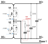
Another option is to add/modify RC snubber. There is already an RC snubber on the board, with an option to add another RC snubber across the lower switch. Should I add RC snubber across the lower switch? I have seen online pictures with only snubber across DC+/- or across each switch in a leg, but my configuration only has an option across the lower leg and/or across DC+/-.
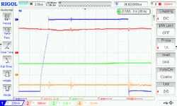
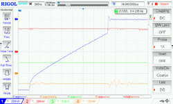
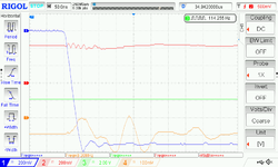
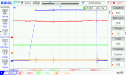
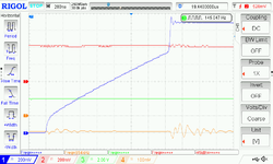
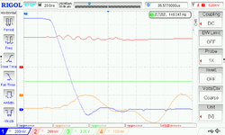
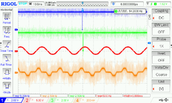
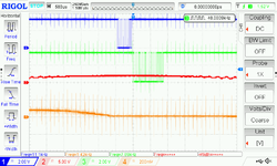
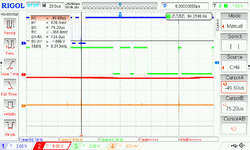
Noise is shown in oscillograms below (different time division: 10 ms, 500 us and 20 us, respectively). I don't see much of a ringing, just a spike at 8 kHz. Also, the inverter switching frequency is 4 kHz, but the noise is at 8 kHz?! Not sure why is that.
Ch1 is Rx signal
Ch2 is Tx signal
The reason is that a high noise causes the TI control card serial emulator to reset. I am losing the serial communication connection between the local PC and the control card at higher power. TI engineers advised me to try to use more robust emulators ($$). Before doing that, is there a way to reduce switching noise?
I have already reduced gate resistance (Rgon and Rgoff) by 1/3. The noise reduced, but not significantly. I can try to reduce it even more, but I read this can lead to increased switching losses.
Another option is to add/modify RC snubber. There is already an RC snubber on the board, with an option to add another RC snubber across the lower switch. Should I add RC snubber across the lower switch? I have seen online pictures with only snubber across DC+/- or across each switch in a leg, but my configuration only has an option across the lower leg and/or across DC+/-.

Noise is shown in oscillograms below (different time division: 10 ms, 500 us and 20 us, respectively). I don't see much of a ringing, just a spike at 8 kHz. Also, the inverter switching frequency is 4 kHz, but the noise is at 8 kHz?! Not sure why is that.
Ch1 is Rx signal
Ch2 is Tx signal


Last edited:
